
Fiber-optic gyroscope inertial measurement spatial four-point vibration damping system

A technology of inertial measurement and fiber optic gyroscope, which is applied in Sagnac effect gyroscope, navigation through speed/acceleration measurement, etc., can solve the problems of poor thermal insulation performance, achieve convenient center of mass adjustment, broad market application prospect, and wide application range wide effect

Inactive Publication Date: 2018-02-09
BEIJING AEROSPACE TIMES OPTICAL ELECTRONICS TECH
View PDF4 Cites 14 Cited by
  • Summary
  • Abstract
  • Description
  • Claims
  • Application Information

AI Technical Summary

Problems solved by technology

[0006] The technical problem solved by the present invention is: to overcome the deficiencies of the prior art, the present invention provides a four-point vibration reduction system for the inertial measurement space of the fiber optic gyroscope. The heavy installation position provides an operating space for the subsequent fine-tuning of the center of mass, improves the vibration reduction performance of the fiber optic gyroscope, and makes up for the poor adaptability to high-frequency vibration of the traditional fiber optic gyroscope inertial measurement device; The temperature control of the components realizes the high-precision measurement of the meter in the whole temperature range, and solves the problem of poor thermal insulation performance of the traditional fiber optic gyroscope inertial measurement device

Method used


Image

  • Fiber-optic gyroscope inertial measurement spatial four-point vibration damping system
  • Fiber-optic gyroscope inertial measurement spatial four-point vibration damping system
  • Fiber-optic gyroscope inertial measurement spatial four-point vibration damping system

Examples


Embodiment Construction

[0029] In order to make the solution of the present invention clearer, the present invention will be further described below in conjunction with the accompanying drawings and specific embodiments:

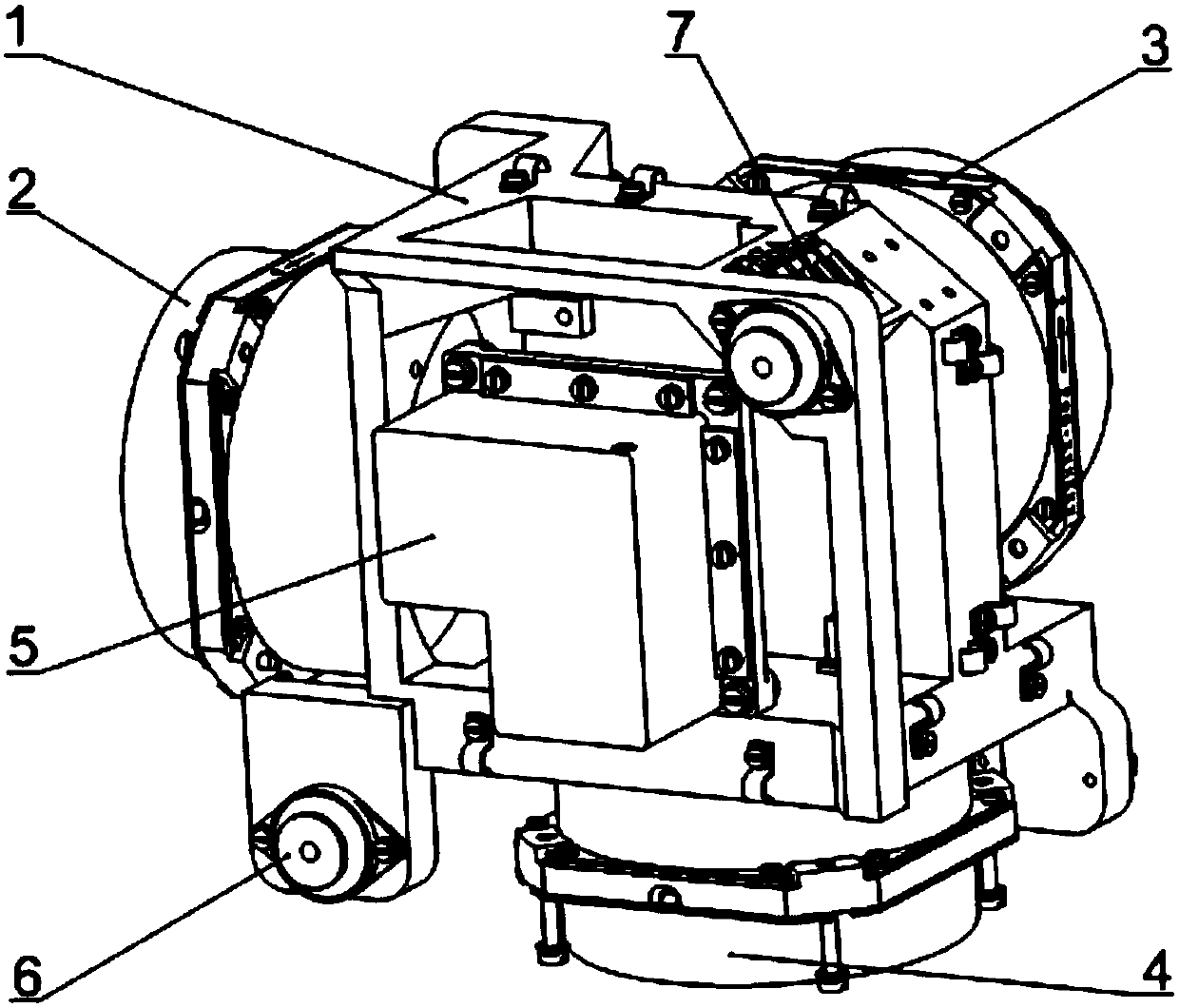
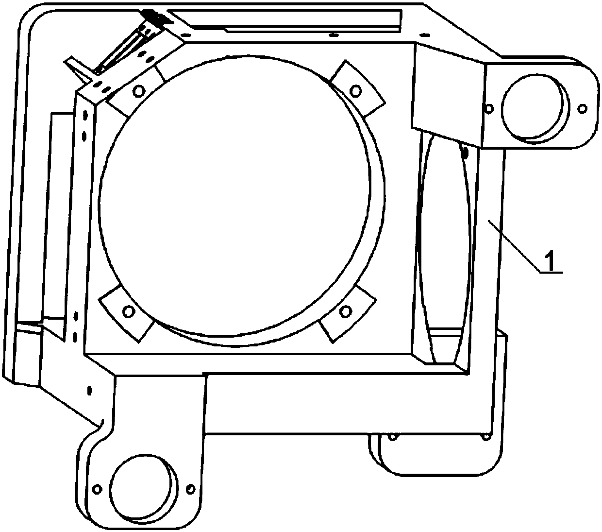
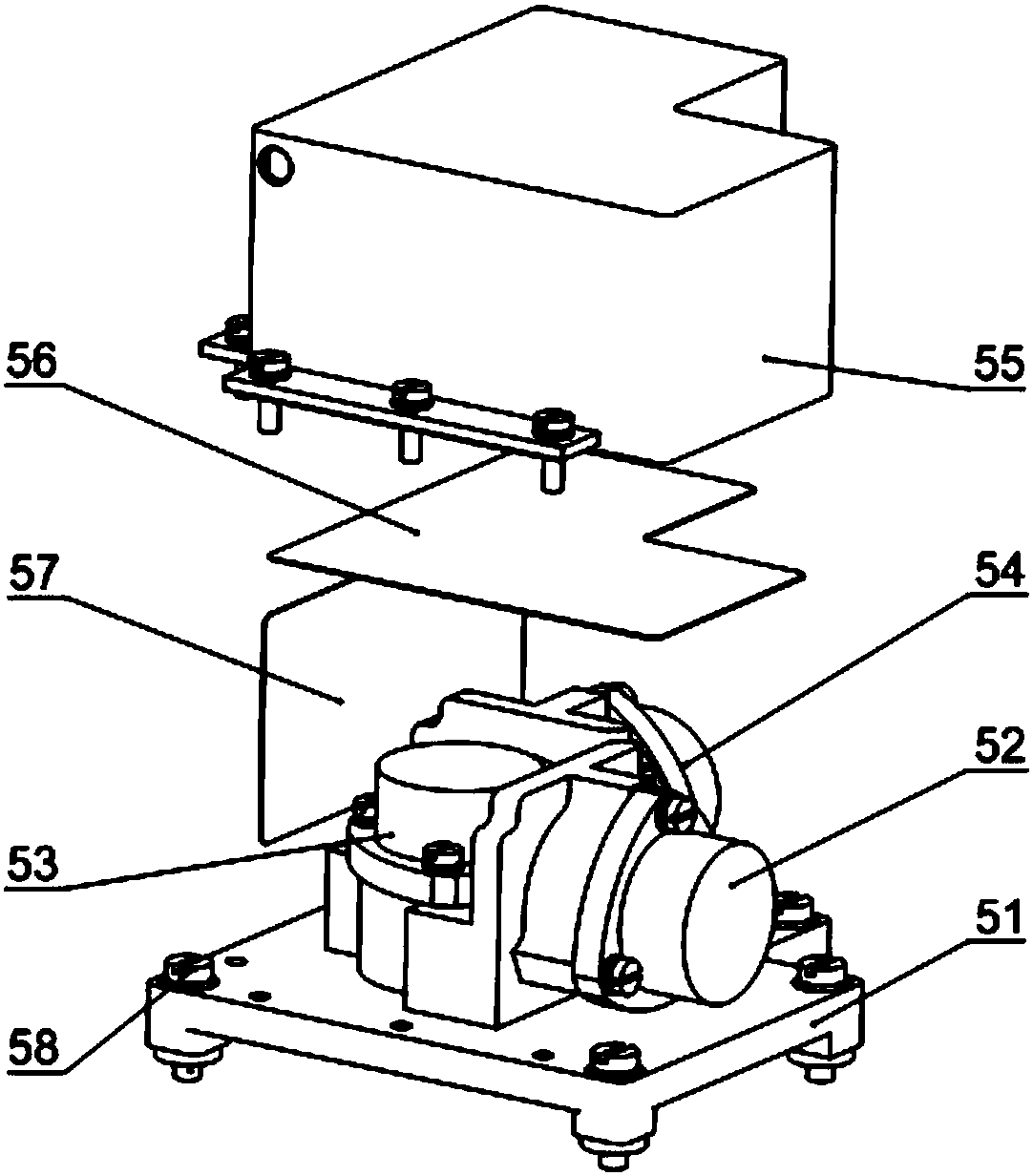
[0030] Such as Figure 1~2 As shown, a fiber optic gyroscope inertial measurement space four-point vibration reduction system includes a body 1, a first gyroscope 2, a second gyroscope 3, a third gyroscope 4, a meter assembly 5 and a shock absorber 6; the body 1 It is a regular hexahedron frame, the first gyroscope 2, the second gyroscope 3 and the third gyroscope 4 are all fiber optic gyroscopes, and the first gyroscope 2, the second gyroscope 3 and the third gyroscope 4 are respectively installed on the body 1 On three mutually perpendicular surfaces, the axes of the first gyroscope 2, the second gyroscope 3 and the third gyroscope 4 intersect at one point to form a spatial rectangular coordinate system, and the meter assembly 5 is fixedly connected between the body 1 and the sec...


PUM


Abstract

The invention discloses a fiber-optic gyroscope inertial measurement spatial four-point vibration damping system. The system comprises a main body, gyroscopes, an accelerometer assembly and shock absorbers. The main body is a hexahedral frame. The three gyroscopes are installed on three surfaces, perpendicular to each other, of the main body. The axes of the three gyroscopes intersect at a point to form a space rectangular coordinate system. The accelerometer assembly is fixedly connected to the surface of the main body opposite to the gyroscopes. The shock absorbers are respectively arrangedat four diagonal points of the main body. The geometric centers of the shock absorbers coincide with the centroid of the system. The main body is provided with the shock absorbers and a weight installation position, provides a space for later centroid fine adjustment, improves fiber-optic gyroscope vibration damping performances and solves the problem that the conventional fiber-optic gyroscope inertial measurement device has poor high frequency vibration adaptability. Through the temperature control of the main body and the accelerometer assembly, the high-precision measurement of the accelerometer assembly in the whole temperature range is realized and the problem of poor insulation performances of the conventional fiber-optic gyroscope inertial measurement device is solved.

Description

technical field [0001] The invention relates to a four-point vibration reduction system for a fiber optic gyro inertial measurement space, especially a high-precision inertial measurement device suitable for navigation, guidance and control of reentry aircraft, and belongs to the technical field of fiber optic gyro inertial measurement devices. Background technique [0002] Aircraft, as a symbol of high-tech development, plays an extremely important role in my country's national defense and economic construction. The accuracy of attitude and speed measurement is the prerequisite for the stable and reliable operation of the aircraft. It directly affects the accuracy and performance of the attitude control system. [0003] Fiber optic gyroscope is an all-solid-state optical inertial instrument, which has many characteristics such as high reliability, long life, light and small size, low power consumption, fast dynamic response, wide precision coverage, fast start-up, direct dig...

Claims


Application Information

Patent Timeline
Patent Type & Authority Applications(China)
IPC IPC(8): G01C19/72G01C21/18
CPCG01C19/72G01C21/18
Inventor 谢海峰宁晓戈杨鹏冯文龙王宁袁韬刘朝阳张称称
Owner BEIJING AEROSPACE TIMES OPTICAL ELECTRONICS TECH
Learn More