Eureka AIR delivers breakthrough ideas for toughest innovation challenges, trusted by R&D personnel around the world.

Energy recycling valve group and hydraulic excavator

A hydraulic excavator, energy recovery technology, applied in mechanical equipment, servo motor components, fluid pressure actuating devices, etc., can solve problems such as waste of potential energy when the boom is lowered, reduce the output flow of the main pump, and cause cavitation. The operability and stability, the effect of ensuring the smooth operation and effective recovery

Active Publication Date: 2018-02-09
JIANGSU XCMG CONSTR MASCH RES INST LTD
View PDF6 Cites 5 Cited by
  • Summary
  • Abstract
  • Description
  • Claims
  • Application Information

AI Technical Summary

Problems solved by technology

Ordinary hydraulic excavators do not recycle the downward potential energy of the boom, so that the downward potential energy of the boom is lost in the form of heat energy at the throttle port. This lost energy will cause the oil temperature of the system to rise, causing cavitation and other phenomena
In addition, the working cycle of hydraulic excavators is short and the frequency is high, so that the recyclable boom lowering potential energy is considerable, so there is an urgent need to develop an energy recovery valve for hydraulic excavators
[0003] At present, some well-known construction machinery companies at home and abroad have done relevant research on the energy recovery of excavator hydraulic systems. There is an energy-saving hydraulic valve for hydraulic excavators. By increasing the width of the gear slot and the diameter of the valve core, the The oil flow area can reduce the pressure loss of the flow channel and achieve the purpose of energy saving. However, the energy-saving hydraulic valve is only generally optimized on the basis of the original main valve, without substantial innovation, and a large amount of energy is lost when the boom is lowered. The potential energy has not been recycled, so that a large amount of boom lowering potential energy is wasted; there is also an excavator oil-hydraulic hybrid control system with energy recovery and conversion. The flow in the pump is connected to the stick cylinder through the two-position two-way valve to realize direct energy conversion, thereby reducing the output flow of the main pump and saving energy. However, this method cannot solve the problem caused by the two-position two-way switch. The problem of pressure shock and flow instability affects the coordination and controllability of the compound action of the whole vehicle

Method used


Image

  • Energy recycling valve group and hydraulic excavator
  • Energy recycling valve group and hydraulic excavator
  • Energy recycling valve group and hydraulic excavator

Examples


Embodiment Construction

[0032] The technical solutions in the embodiments will be clearly and completely described below in conjunction with the drawings in the embodiments of the present invention. Obviously, the described embodiments are only a part of the embodiments of the present invention, rather than all the embodiments. Based on the embodiments of the present invention, all other embodiments obtained by those of ordinary skill in the art without creative work fall within the protection scope of the present invention.

[0033] In the description of the present invention, it should be understood that the terms "center", "transverse", "longitudinal", "front", "rear", "left", "right", "upper", "lower", " The orientation or positional relationship indicated by "vertical", "horizontal", "top", "bottom", "inner", "outer" etc. is based on the orientation or positional relationship shown in the drawings, and is only for the convenience of describing the present invention and The description is simplifie...


PUM


Abstract

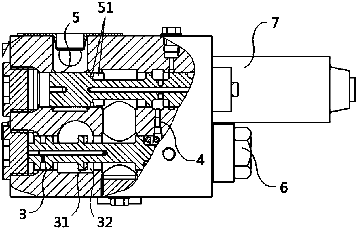
The invention relates to an energy recycling valve group and a hydraulic excavator. The energy recycling valve group comprises a switch assembly, a compensating valve (3) and a main reversing valve (5); the switch assembly is communicated with an oil outlet of a to-be-recycled oil way; the compensating valve (3) is connected between the switch assembly and the main reversing valve (5), and is usedfor controlling opening or closing of the energy recycling valve group; the compensating valve (3) is used for keeping the before and after pressure difference of the main reversing valve (5) constant; and the main reversing valve (5) can be communicated with an oil inlet of a receiving oil way, so that hydraulic oil of the to-be-recycled oil way can be recycled to the receiving oil way. According to the energy recycling valve group, by means of the switch assembly, the compensating valve and the main reversing valve, the hydraulic oil of the to-be-recycled oil way can be recycled into the receiving oil way and an executing element connected with the receiving oil way, energy recycling is achieved, and energy waste is avoided; and the compensating valve can guarantee that the before and after pressure difference of the main reversing valve constant, the flow of the main reversing valve is made stable, and therefore the action stability of an oil supply element is guaranteed.

Description

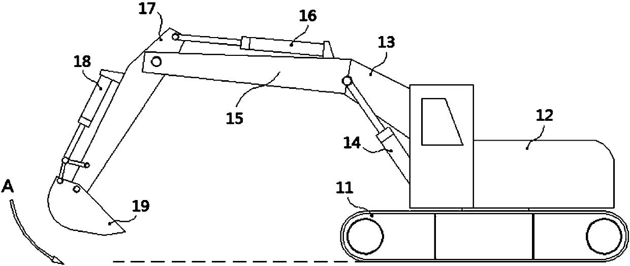
Technical field [0001] The invention relates to the technical field of engineering machinery, in particular to an energy recovery valve group and a hydraulic excavator. Background technique [0002] Hydraulic excavator is a widely used construction machinery. The quality of its working device accounts for about 1 / 4 of the total mass of the whole machine. During the excavation operation, the working device has to undergo a lift in almost every operation cycle. Therefore, most of the energy of the system is consumed on the boom and the stick, and the sum of the energy consumed by the two exceeds 50% of the total output energy of the hydraulic pump. Ordinary hydraulic excavators do not recycle the boom down potential energy, so that the boom down potential energy is lost in the form of thermal energy at the throttle. This lost energy will cause the system oil temperature to rise, causing cavitation and other phenomena. In addition, the working cycle of hydraulic excavators is short...

Claims


Application Information

Patent Timeline
Patent Type & Authority Applications(China)
IPC IPC(8): F15B13/02F15B11/08
CPCF15B11/08F15B13/022
Inventor 王钦杜璇费树辉
Owner JIANGSU XCMG CONSTR MASCH RES INST LTD
Why Eureka
Eureka Blog
Learn More