
Non-leakage pressure compensated electro-proportional throttle valve

A pressure compensation, electric proportional technology, applied in the field of hydraulic valves, can solve the problems of unsustainable load, large leakage, non-pressure maintaining of valves, etc., and achieve the effect of reducing leakage

Active Publication Date: 2018-08-24
浙江三尚智迪科技有限公司
View PDF13 Cites 0 Cited by
  • Summary
  • Abstract
  • Description
  • Claims
  • Application Information

AI Technical Summary

Problems solved by technology

[0003] The technical problem to be solved by the present invention is to provide a non-leakage pressure-compensated electric proportional throttle valve to solve the problems in the existing load lifting hydraulic system that the valve does not maintain pressure, the load cannot be maintained, and the leakage is large

Method used


Image

  • Non-leakage pressure compensated electro-proportional throttle valve
  • Non-leakage pressure compensated electro-proportional throttle valve
  • Non-leakage pressure compensated electro-proportional throttle valve

Examples


Embodiment Construction

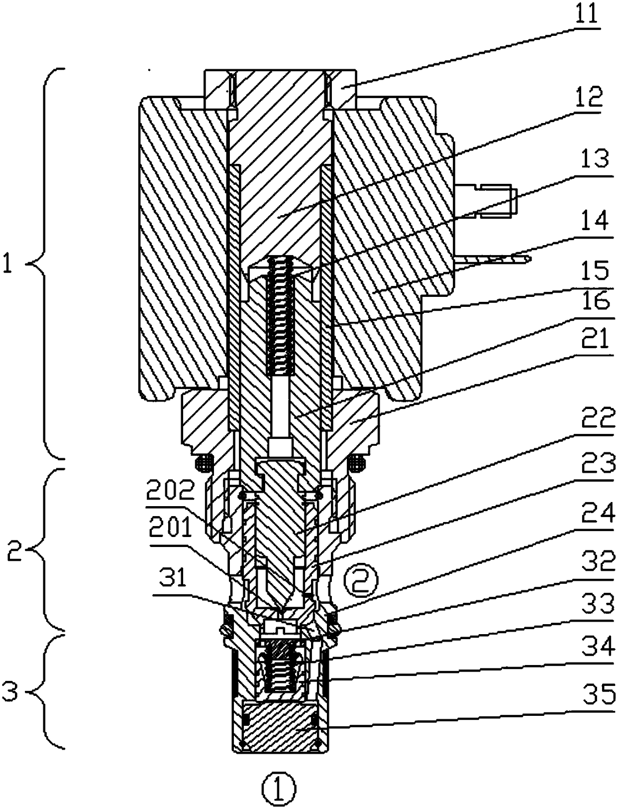
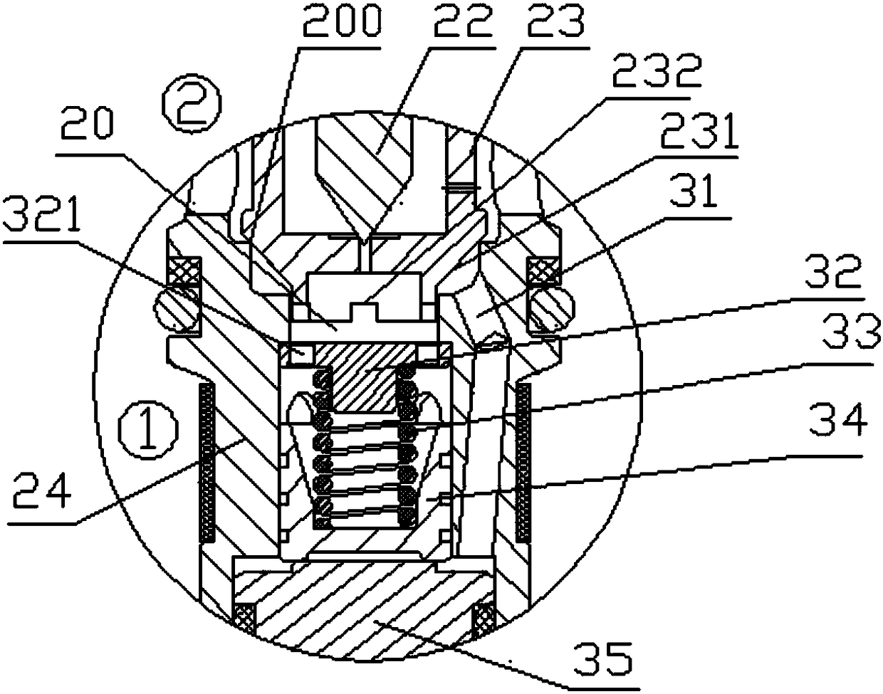
[0020] Such as figure 1 and figure 2 As shown, the non-leakage pressure-compensated electric proportional throttle valve includes proportional solenoid 1, main valve 2 and pressure compensator 3, which form a two-way non-leakage threaded cartridge valve, which can realize direction control and proportional flow adjustment Function, non-leakage function when fully closed, constant flow during work and many other functions.

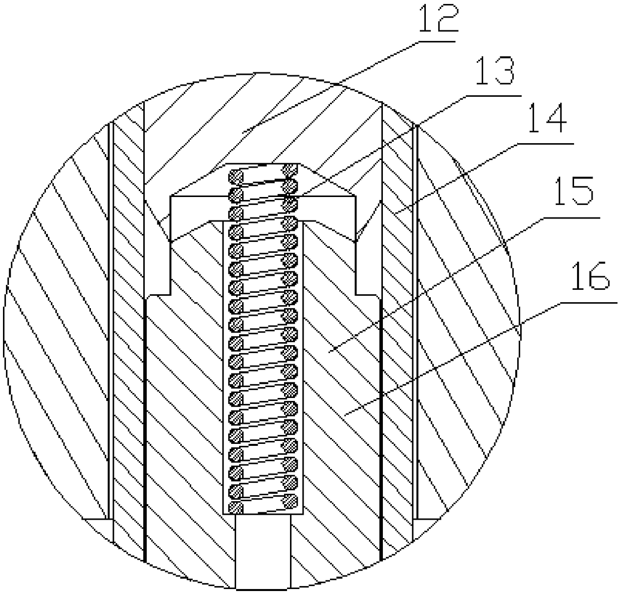
[0021] Among them, the proportional electromagnet 1 includes a magnetic isolation sleeve 15, a front end 21 located on the front side of the magnetic isolation sleeve 15 and connected to the main valve 2, a tail end 12 located on the rear side of the magnetic isolation sleeve, and an armature located inside the magnetic isolation sleeve. 16 and the first spring 13 that is located between the armature 16 and the tail to elastically press the armature forward, and the locking nut 11 locks and fixes the coil 14 on the magnetic isolation sleeve 15 . Tail 12 ...


PUM


Abstract

The invention discloses a leak-tight pressure compensation electric proportional throttle valve. The valve comprises a proportion electromagnet, a master valve and a pressure compensator. The master valve comprises a valve sleeve. One side of the valve sleeve, which faces a pressure compensation cavity, is provided with an opening. A master valve spool cavity which is placed in a master valve spool is arranged at the rear portion of an inner hole of the valve sleeve. A valve port which is opened and closed by the master valve spool is arranged in the valve sleeve inner hole between the pressure compensation cavity and the master valve spool cavity. A pilot cavity containing a pilot valve is arranged behind the master spool. Two holes are formed in a section of the valve sleeve facing the master valve spool cavity. The section located between a cylinder sealing section and a conical surface section, which is in the master valve spool, is provided with a damping conducting hole which is communicated with a frontal sensitivity cavity of the pilot cavity. A pilot damping hole which is communicated with the sensitivity cavity is formed in the front end of the master spool. An oil guide hole is formed in the valve sleeve. According to the leak-tight pressure compensation electric proportional throttle valve, the proportion electromagnet is used for achieving the function of flow adjustment, the master valve and the pressure compensation valve are in serial connection, thus all the flow passing through the master valve must pass through the pressure compensator for pressure compensation.

Description

technical field [0001] The invention relates to a hydraulic valve, in particular to a pressure compensation electric proportional throttle valve. Background technique [0002] In most load lifting systems, a reversing valve is usually used to lower the load, and the lowering speed is generally adjusted through the opening of the valve, but in the case of large load changes, the speed will be slow and fast, causing system instability . Moreover, these reversing valves are all in the form of slide valves. When closing or stopping the load, the load cannot be kept at a certain position and will slide down, and the pressure in the cavity cannot be well maintained when pressure maintenance is required. Or the flow valve composed of a valve in the form of a cone valve and a pressure compensator also has problems such as no pressure retention, load retention, large leakage, and large volume. Contents of the invention [0003] The technical problem to be solved by the present in...

Claims


Application Information

Patent Timeline
Patent Type & Authority Patents(China)
IPC IPC(8): F15B13/02F15B13/01
CPCF15B13/015F15B13/022F15B13/026
Inventor 单俊峰罗占涛姚海峰
Owner 浙江三尚智迪科技有限公司
Learn More