Eureka AIR delivers breakthrough ideas for toughest innovation challenges, trusted by R&D personnel around the world.

Method for controlling heat-humidity ratio of air conditioning system and fixed heat-humidity ratio type surface cooler

An air-conditioning system, heat-humidity ratio technology, applied in heating and ventilation control systems, refrigerators, heating methods, etc., can solve problems such as loss of control, and achieve the effect of simplifying the automatic control system, improving comfort, and reducing energy consumption

Active Publication Date: 2015-03-18
GUANGZHOU DESIGN INST
View PDF11 Cites 0 Cited by
  • Summary
  • Abstract
  • Description
  • Claims
  • Application Information

AI Technical Summary

Problems solved by technology

At present, the heat exchange capacity of the existing surface cooler at full load has been fully tapped, but the dehumidification performance is positively correlated with the opening of the electric two-way valve connected to it, and the usual annual indoor heat-humidity ratio is also large in summer. The transitional season is small. Therefore, in most occasions where air-conditioning units are used, the coil selected according to the design working conditions can ensure the indoor humidity when the room temperature is guaranteed, except in the hotter summer. time is out of control

Method used


Image

  • Method for controlling heat-humidity ratio of air conditioning system and fixed heat-humidity ratio type surface cooler
  • Method for controlling heat-humidity ratio of air conditioning system and fixed heat-humidity ratio type surface cooler
  • Method for controlling heat-humidity ratio of air conditioning system and fixed heat-humidity ratio type surface cooler

Examples


specific Embodiment 1

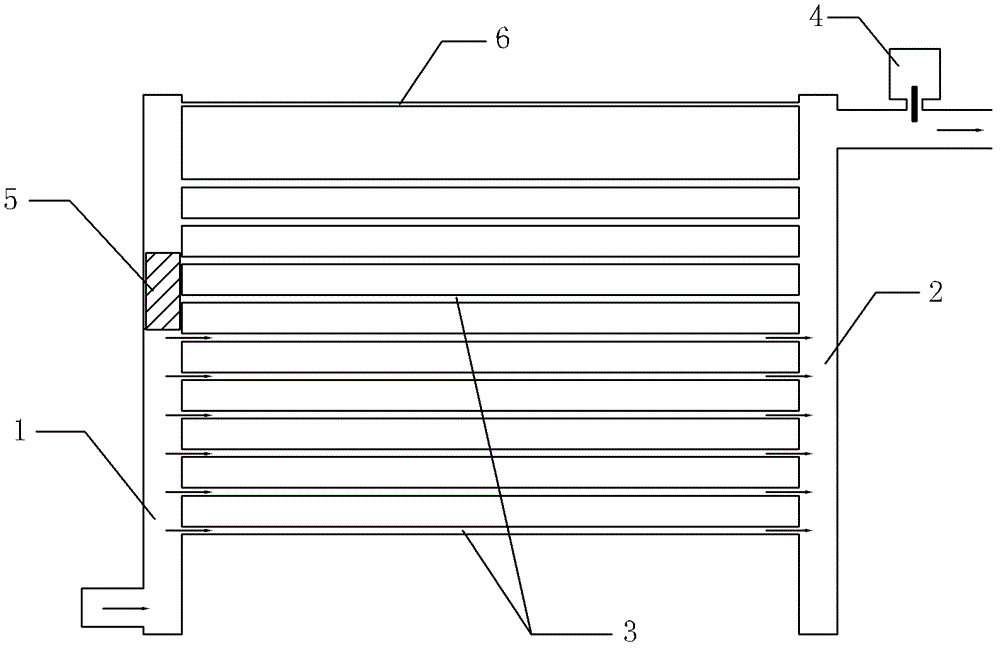
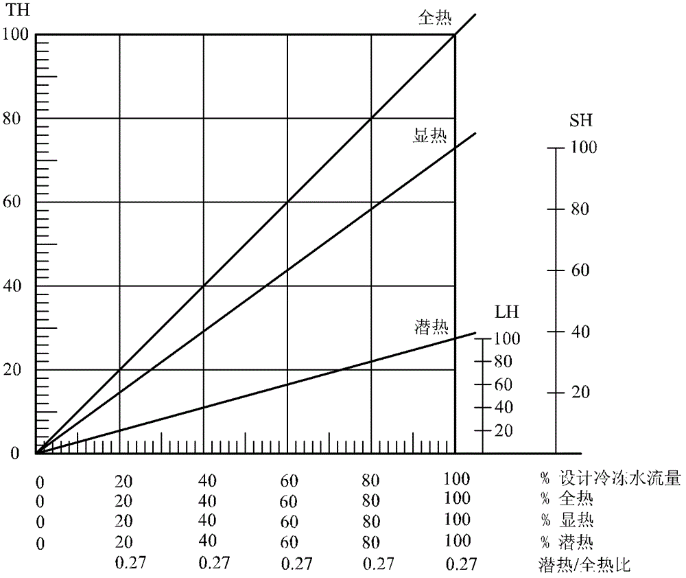
[0027] figure 1 and figure 2 Constitute the specific embodiment 1 of the present invention.

[0028] refer to figure 2 , the method for controlling the heat-humidity ratio of the air conditioning system described in this embodiment is characterized in that:

[0029] 1) Install a constant heat-humidity ratio surface cooler in the air-conditioning system, so that the air-conditioning system can block chilled water from flowing into non-essential coils through the piston when the air-conditioning system is under partial load, so as to limit the heat conduction of a part of the coils with a dominant proportion of sensible heat load ;

[0030] 2) Set a gravity piston and a pressure signal tube in the water supply main pipe of the constant heat-humidity ratio surface cooler, and control the pressure difference in the water supply main pipe of the constant heat-humidity ratio surface cooler through the gravity piston and pressure signal pipe The gravity piston is selected thro...


PUM


Abstract

The invention discloses a method for controlling the heat-humidity ratio of an air conditioning system and a fixed heat-humidity ratio type surface cooler. The fixed heat-humidity ratio type surface cooler comprises a chilled water supply pipe (1) and a water return pipe (2), wherein the water outlet of the chilled water supply pipe (1) is connected with the water inlet of the water return pipe (2) through a plurality of coil pipes (3) which are longitudinally arranged; and an electric two-way valve (4) is arranged at the water outlet of the water return pipe (2). The fixed heat-humidity ratio type surface cooler is characterized in that: a gravity piston (5) is arranged in the chilled water supply pipe (1), a pressure difference signal pipe (6) is arranged between the chilled water supply pipe (1) and the water return pipe (2), and the pressure difference signal pipe (6) is arranged at the upper part of the coil pipes (3). According to the invention, because the fixed heat-humidity ratio type surface cooler is arranged in the air conditioning system, the situation that the humidity of the air conditioning system in partial load is out of control can be avoided; and the fixed heat-humidity ratio type surface cooler has the beneficial effects of keeping the pressure difference of the coil pipes and the temperature difference of inlet water and outlet water constant, simplifying an automatic control system and improving the air conditioning efficiency and is particularly suitable for occasions with large temperature difference and low pressure difference of coil pipes.

Description

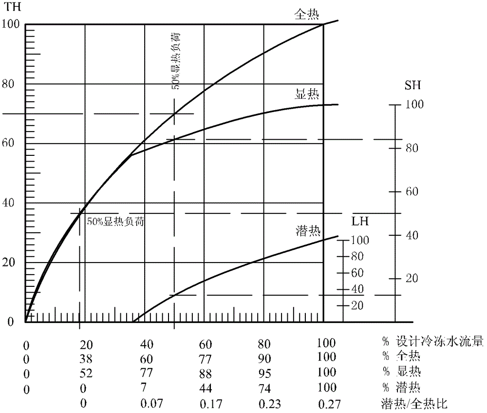
technical field [0001] The invention relates to a method for controlling the heat-humidity ratio of an air-conditioning system and a constant heat-humidity ratio surface cooler, belonging to the technical field of air-conditioning or central air-conditioning systems. Background technique [0002] In the prior art, the traditional method of controlling indoor temperature under partial load: such as image 3 As shown, by controlling the electric two-way valve to reduce the amount of water entering the coil, the chilled water flow has a nonlinear relationship with the cooling capacity of the cooling coil. To achieve 50% sensible heat of the coil, about 20% of the chilled water flow is required. In the existing control, the total flow of cooling water is proportional to the pipe flow rate of the coil. In order to make the sensible heat load 50% , the flow rate is kept above the limit of laminar flow rate, which is 0.25m / s, and it is necessary to select the water velocity of the ...

Claims


Application Information

Patent Timeline
Patent Type & Authority Patents(China)
IPC IPC(8): F24F11/02F25B39/00
Inventor 李觐
Owner GUANGZHOU DESIGN INST
Why Eureka
Eureka Blog
Learn More