Drill pipe device of hydraulic pile driver
A technology of pile driver and drill pipe, which is applied in the direction of drill pipe, driving device of rotary combined drilling, drill bit, etc., can solve the problem that the drill pipe and drill rod should be broken, so as to improve the service life, save the use cost, and reduce the impact force. big effect
- Summary
- Abstract
- Description
- Claims
- Application Information
AI Technical Summary
Problems solved by technology
Method used
Image

Examples
Embodiment 1
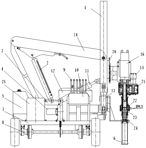
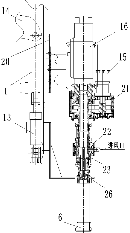
[0074] Embodiment 1: The hydraulic drilling working device of the pile driver includes: hydraulic hammer 16, drill pipe hydraulic motor 15, machine head assembly 21, rotary joint assembly assembly 22, drill pipe assembly assembly 23, drill bit 6, air compressor 25. The drill pipe positioning sleeve 24 and the gear box assembly 26; the hydraulic hammer 16 is connected with the slide plate 20 through the hammer splint, and the machine head assembly 21 is located under the hydraulic hammer 16 and connected with the hydraulic hammer 16. There is a gearbox assembly 26 on one side; or the head assembly 21 is connected to the slide plate 20; the drill pipe hydraulic motor 15 is connected to the head assembly 21; the head assembly 21, the rotary joint assembly assembly 22 and the drill pipe assembly The assembly 23 is sequentially connected, the chisel of the machine head assembly 21 and the spline shaft 4-1 of the drill bit 6 at the center of the machine head assembly 21, the rotary j...
Embodiment 2
[0085] Embodiment 2: The drill rod assembly includes: drill rod 1-12, intake column 2-8 and long drill rod 2-9; drill rod 1-12, intake column 2-8 and long drill rod 2 -9 sequentially overlapped, the drill rod 1-12 is overlapped with the hydraulic hammer at the upper end, and the long drill rod 2-9 is overlapped with the drill bit 6 at the lower end. The grooves on the circumference of the drill rod 1-12, the air intake column 2-8 and the grooves on the end faces and the through holes in the long drill rod 2-9 are matched to form a continuous air passage.
[0086] The drill rod is a cylinder on which there is a spacer.
[0087] The long drill rod is a cylinder with a through hole in the center of the cylinder.
[0088] The air intake column is a cylinder, and longitudinal grooves are evenly distributed on the outer wall of the cylinder, the longitudinal grooves run through the outer wall of the cylinder, and the end surface of the cylinder has a groove.
[0089] Others are th...
Embodiment 3
[0090] Embodiment 3: The drill rod 1-12 of the drill rod assembly, the long drill rod 2-9 and the air intake column 2-8 are sequentially overlapped, the drill rod 1-12 is overlapped with the hydraulic hammer at the upper end, and the air intake The column 2-8 overlaps with the drill bit 6 at the lower end.
[0091] The longitudinal grooves on the circumference of the drill rod 1-12, the long drill rod 2-9 and the grooves and through holes on the intake column 2-8 are matched to form a continuous air passage.
[0092] The drill rod is a cylinder on which there is a spacer.
[0093] The long drill rod is a cylinder, and grooves are distributed on the outer wall of the cylinder at intervals, and the grooves are longitudinally and intermittently distributed on the cylinder.
[0094] The air inlet column is a cylinder with unequal diameters, one end has a large diameter, and the other end has a small diameter. There is a groove on the end surface of the end of the cylinder with a ...
PUM
 Abstract
Description
Claims
Application Information
 - R&D
- Intellectual Property
- Life Sciences
- Materials
- Tech Scout
- Unparalleled Data Quality
- Higher Quality Content
- 60% Fewer Hallucinations
Browse by: Latest US Patents, China's latest patents, Technical Efficacy Thesaurus, Application Domain, Technology Topic, Popular Technical Reports.
© 2025 PatSnap. All rights reserved.Legal|Privacy policy|Modern Slavery Act Transparency Statement|Sitemap|About US| Contact US: help@patsnap.com