Automatic tin soldering device of LED luminescent light bar

A technology of automatic welding and light-emitting lamps, which is applied in the direction of tin feeding devices, auxiliary devices, welding equipment, etc., can solve the problems of unfavorable production cost saving, product reliability improvement, low production efficiency, and weak connection, etc. Tightening and opening are convenient and fast, accurate control and guarantee, and the effect of improving connection reliability

Active Publication Date: 2018-02-06
FOSHAN ELECTRICAL & LIGHTING
View PDF8 Cites 2 Cited by
  • Summary
  • Abstract
  • Description
  • Claims
  • Application Information

AI Technical Summary

Problems solved by technology

[0002] In the LED direct-emitting panel light, the LED illuminant is usually welded on the auxiliary conductive plate by a plurality of light-emitting strips on the hard substrate, such as figure 1 and 2 As shown, the LED illuminant 100 is provided with solder joints 10, and the auxiliary conductive plate 200 is provided with copper foil solder joints 20, and then the solder joints 10 and copper foil solder joints 20 are welded together by wires to realize electrical connection and fixed connection. , this welding method is a two-point welding method (one point is the solder point on the LED luminous body, and the other point is the copper foil solder point on the auxiliary conductive plate), and it is very difficult to realize automatic welding. Therefore, this type of product is currently All are welded by hand, the production efficiency is low, and the labor cost is high. On the other hand, because the surface of the solder joint and the copper foil solder joint are flat, a large amount of welding material is wasted, and the connection is not firm, which is not conducive to saving production costs and With the improvement of product reliability, it is necessary to change the structure of the LED light bar and realize the automatic soldering device to solve the above problems

Method used


Image

  • Automatic tin soldering device of LED luminescent light bar
  • Automatic tin soldering device of LED luminescent light bar
  • Automatic tin soldering device of LED luminescent light bar

Examples


Embodiment Construction

[0029] In order to make the object, technical solution and advantages of the present invention clearer, the present invention will be further described in detail below in conjunction with the accompanying drawings. It is only stated here that the words for directions such as up, down, left, right, front, back, inside, and outside that appear or will appear in the text of the present invention are only based on the accompanying drawings of the present invention, and are not specific to the present invention. limited.

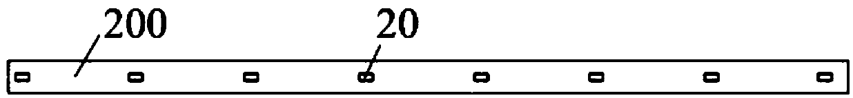
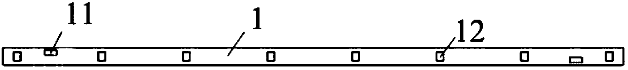
[0030] See attached Figure 3-7 , the invention discloses an automatic soldering device for an LED light bar, comprising a soldering mechanism 3 for welding an LED light bar 1 and an auxiliary conductive plate 2, a tin feeding mechanism 4 connected to the soldering mechanism 3, a support Mechanism 5, a transmission mechanism 6 located on the support mechanism 5 and an installation mechanism 7 located on the transmission mechanism 6;

[0031] The installation me...


PUM


Abstract

The invention discloses an automatic tin soldering device of an LED luminescent light bar. The device comprises a tin soldering mechanism used for welding the LED luminescent light bar and an auxiliary conductive plate, a tin conveying mechanism connected with the tin soldering mechanism, a supporting mechanism, a conveying mechanism on the supporting mechanism, and a mounting mechanism on the conveying mechanism; the mounting mechanism mounts the LED luminescent light bar and the auxiliary conductive plate, the LED luminescent light bar at least comprises welding points, the auxiliary conductive plate comprises through holes and metal conductive layers, and the through holes run through the auxiliary conductive plate. Through the through hole structure on the auxiliary conductive plate, the tin soldering mechanism, the tin conveying mechanism, the supporting mechanism, the conveying mechanism and the mounting mechanism, automatic tin soldering of the LED luminescent light bar is achieved, the production efficiency is high, the tin soldering quality is guaranteed, and thus bonding reliability of the welding points, the through holes and the metal conductive layers is guaranteed.

Description

technical field [0001] The invention relates to the technical field of processing equipment for LED light strips, in particular to an automatic soldering device for LED light strips. Background technique [0002] In the LED direct-emitting panel light, the LED illuminant is usually welded on the auxiliary conductive plate by a plurality of light-emitting strips on the hard substrate, such as figure 1 and 2 As shown, the LED illuminant 100 is provided with solder joints 10, and the auxiliary conductive plate 200 is provided with copper foil solder joints 20, and then the solder joints 10 and copper foil solder joints 20 are welded together by wires to realize electrical connection and fixed connection. , this welding method is a two-point welding method (one point is the solder point on the LED luminous body, and the other point is the copper foil solder point on the auxiliary conductive plate), and it is very difficult to realize automatic welding. Therefore, this type of p...

Claims


Application Information

Patent Timeline
Patent Type & Authority Applications(China)
IPC IPC(8): B23K3/00B23K3/06B23K3/08B23K37/04
CPCB23K3/00B23K3/0607B23K3/08B23K3/087B23K2101/36
Inventor 王伟张勇王学强杨智良李文福
Owner FOSHAN ELECTRICAL & LIGHTING
Why Eureka
Try Eureka