
Pulse wave sensor, pulse wave monitoring method and wearable device

A technology of pulse wave and sensor, applied in the field of pulse wave monitoring, can solve the problems of high power consumption, large interference signal, complicated operation, etc., and achieve the effect of improving utilization rate and signal-to-noise ratio

Pending Publication Date: 2018-02-06
挚感(上海)光子科技有限公司
View PDF2 Cites 3 Cited by
  • Summary
  • Abstract
  • Description
  • Claims
  • Application Information

AI Technical Summary

Problems solved by technology

[0005] In addition, the pulse wave monitors in the medical market are relatively large in size and can only be used for single-point or short-term monitoring of the pulse. The data cannot be transmitted wirelessly, the interference signal is large, and the operation is complicated and requires the measurement of professionals. The result is easily distorted due to subjective factors
However, pulse wave monitors on the home market have problems such as inaccurate measurement results, high power consumption, and insufficient standby time, which cannot meet people's needs.

Method used


Image

  • Pulse wave sensor, pulse wave monitoring method and wearable device
  • Pulse wave sensor, pulse wave monitoring method and wearable device
  • Pulse wave sensor, pulse wave monitoring method and wearable device

Examples


Embodiment Construction

[0059] Embodiments of the present invention will now be described in detail with reference to the accompanying drawings. Wherever possible, the same numbers will be used throughout the drawings to refer to the same or like parts. In addition, although the terms used in the present invention are selected from well-known and commonly used terms, some terms mentioned in the description of the present invention may be selected by the applicant according to his or her judgment, and the detailed meanings thereof are set forth herein described in the relevant section of the description. Furthermore, it is required that the present invention be understood not only by the actual terms used, but also by the meaning implied by each term.

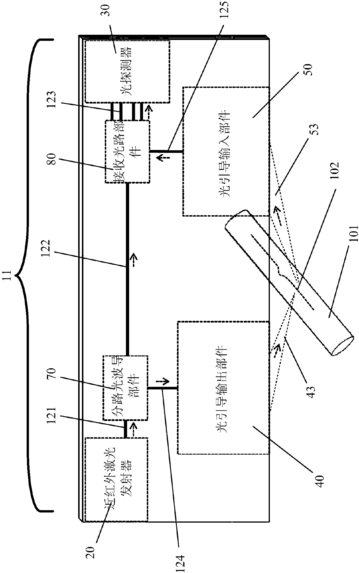
[0060] figure 1 A schematic structural diagram of an embodiment of the pulse wave sensor of the present invention is shown. Such as figure 1 As shown, the present invention provides a pulse wave sensor 11 based on an optical waveguide platform that...


PUM


Abstract

The invention provides an optical scanning pulse wave sensor, a wearable device, an optical scanning wrist-type pulse wave analysis meter, an optical scanning heart rate meter, an optical scanning blood pressure monitoring meter, an optical scanning blood vessel rigidity tester, an optical scanning carotid artery rigidity tester and a pulse wave monitoring method. The pulse wave sensor comprises alaser emitter, a shunting optical waveguide part, a light leading and outputting part, a light leading and inputting part and an optical path receiving part, wherein the laser emitter emits first laser, the shunting waveguide part receives the first laser and shunts the first laser into second laser and reference light; the light leading and outputting part receives and adjusts the second laserto form third laser so that the third laser can be emitted to a blood vessel; the light leading and inputting part receives and adjusts fourth laser reflected from the blood vessel to form fifth laser; the optical path receiving part receives the fifth laser and the reference light, and forms sixth laser after dual-path interference is conducted. According to the optical scanning pulse wave sensor, relevant monitoring equipment and the wearable device, continuous monitoring can be achieved, the precision is high, the effect is good, and the power dissipation is low.

Description

technical field [0001] The invention belongs to the technical field of pulse wave monitoring in electronic medical equipment, relates to the use of optical devices for measurement, and in particular to a pulse wave sensor, a pulse wave monitoring method and a wearable device. Background technique [0002] Cardiovascular disease is the primary disease that currently threatens human health, and the pulse wave of the human body reflects the function of the cardiovascular system. The body's physiology, mental state, physical strength level and other information reflected by the intensity, speed and rhythm of the pulse wave can display personal health status, or serve as auxiliary monitoring for other medical instruments, and provide diagnostic reference for doctors, etc. [0003] Currently, pulse wave monitoring methods mainly use photoplethysmography (PPG) or the principle of piezoelectric sensors to indirectly reflect changes in pulse waves. Photoplethysmography uses the ligh...

Claims


Application Information

Patent Timeline
IPC IPC(8): A61B5/0295A61B5/021A61B5/02
CPCA61B5/0059A61B5/02007A61B5/02125A61B5/0261A61B5/0295A61B5/6802A61B5/681A61B5/72
Inventor 陈伟张晋钟山朱中华
Owner 挚感(上海)光子科技有限公司
Learn More