Self constant current LED lamp filament

A technology for LED filaments and LED lamps, which is applied in the use of semiconductor lamps, cooling/heating devices of lighting devices, lighting and heating equipment, etc., can solve problems such as complex control structures, and achieve the effect of simplifying assembly processes and reducing production costs.

Pending Publication Date: 2018-02-02
SHANGHAI LATRONIX TECH CORP
View PDF0 Cites 2 Cited by
  • Summary
  • Abstract
  • Description
  • Claims
  • Application Information

AI Technical Summary

Problems solved by technology

[0007] In view of the shortcomings of the prior art described above, the purpose of the present invention is to provide a self-constant current LED filament, which is used to solve the problem of complex external control structure of the LED filament lamp in the prior art

Method used


Image

  • Self constant current LED lamp filament
  • Self constant current LED lamp filament
  • Self constant current LED lamp filament

Examples


Embodiment 1

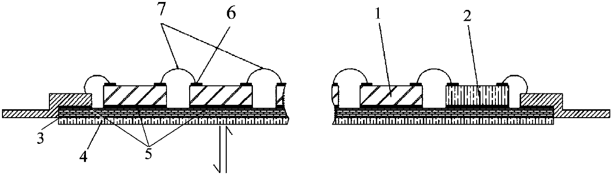
[0065] Such as figure 2 As shown, the present invention provides a self-constant current LED filament, and the self-constant current LED filament at least includes:

[0066] A plurality of LED lamps 1 , a constant current control chip 2 at both ends, a thermally conductive substrate 3 and a high-radiation material layer 4 .

[0067] Such as figure 2 As shown, each LED lamp 1 and the two-end constant current control chip 2 are fixed on the first surface of the heat-conducting substrate 3 .

[0068] Specifically, as image 3 As shown, as an embodiment of the present invention, the LED lamp 1 is a front-mounted LED chip, and each front-mounted LED chip 1 and the constant current control chip 2 at both ends are fixed on the first side of the heat-conducting substrate 3 by an adhesive 5 . On the surface, a welding plate 6 is provided on the surface of each front-mounted LED chip 1 and the constant-current control chip 2 at both ends, and a plurality of front-mounted LED chips ...

Embodiment 2

[0087] The difference between this embodiment and the first embodiment is that the high-radiation material layer 4 is connected to the thermally conductive substrate 3 through chemical bonds, and the chemical bonds include but not limited to metal bonds, ionic bonds, and covalent bonds. In this embodiment, the material of the high-radiation material layer 4 includes but not limited to Nichrome, Nichrome oxide, Nichrome oxide, iron oxide, nickel oxide, bronze, cast iron , white ceramics, copper oxides, lead oxides, steel, steel oxides or aluminum oxides. Any material with a high thermal emissivity that can be formed by mechanical processing or chemical or physical processes and that is chemically bonded to the thermally conductive substrate 3 is suitable for the high-radiation material layer 4 of the present invention, and will not be listed here. .

[0088] Specifically, the formation method of the high radiation material layer 4 includes but not limited to gas phase surface ...


PUM


Abstract

The invention provides a self constant current LED lamp filament. The self constant current LED lamp filament comprises a heat conduction substrate, a plurality of LED lamps fixed to the first surfaceof the heat conduction substrate, two-end constant current control chips and a high radiation material layer formed on the second surface of the heat conduction substrate, and the LED lamps and the two-end constant current control chips are connected in series. According to the self constant current LED lamp filament, the single two-end constant current control chips and LED chips are clustered and placed on the substrate with the radiating function in a series manner, and therefore a self constant current lamp-filament-shaped LED integration light source is formed; the light source rated load voltage and the working current are preset and fixed, and under the condition that the input voltage is larger than the working voltage, the luminous flux within unit time is fixed; an LED lamp bulb capable of meeting different load requirements can be formed through series connection or parallel connection, the requirement for power source input is simplified into rectification and voltage regulating, and work can be done under the condition that current is directly input; and the lamp bulb assembling process can be greatly simplified, a traditional incandescent lamp automatic productionline is directly adopted, and the production cost is reduced.

Description

technical field [0001] The invention relates to the technical field of LED lighting, in particular to a self-constant current LED filament. Background technique [0002] LED is a semiconductor electronic component that can emit light. This electronic component can only emit red light with low luminosity in the early days. With the continuous advancement of technology, it has now developed to the extent that it can emit visible light, infrared rays and ultraviolet rays. Big improvement. LED has the advantages of high efficiency, long life, unbreakable, high switching speed, high reliability, etc. that traditional light sources cannot match, and has been widely used in the fields of indicator lights, displays and lighting. [0003] Due to the unidirectional conduction characteristics of LED, when the reverse voltage is applied to both ends of the LED, the LED lamp is in the reverse dead zone and cannot emit light; when the reverse voltage is too large, the LED is in the rever...

Claims


Application Information

Patent Timeline
Patent Type & Authority Applications(China)
IPC IPC(8): F21K9/20F21V23/00F21V29/503H05B33/08F21Y115/10H05B44/00
CPCF21V23/003F21V29/503H05B45/00Y02B20/30
Inventor 严守平
Owner SHANGHAI LATRONIX TECH CORP
Why Eureka
Try Eureka