Non-electric pulse type sewage lifting pump

A sewage lifting pump and pulse technology, which is applied in the field of non-electric pulse sewage lifting pumps, can solve the problems of sludge floating in sedimentation tanks, difficult construction, and inconvenient sludge discharge, so as to increase the sewage suction capacity and increase the scope of use. Effect

Pending Publication Date: 2018-02-02
重庆林德科技发展有限公司
View PDF11 Cites 0 Cited by
  • Summary
  • Abstract
  • Description
  • Claims
  • Application Information

AI Technical Summary

Problems solved by technology

[0002] In the sewage treatment project, the sludge discharge problem of the sedimentation tank is a problem that people pay more attention to. At present, the sludge discharge device of the sedimentation tank is usually a submersible sewage pump, a conventional air lift device, etc.; but because the submersible sewage pump is installed underwater, this It brings a lot of inconvenience in installation, manufacture and maintenance; especially when the sedimentation tank is an inclined tube settler, since the inclined tube settler needs to cover the pool surface, when the submersible pump needs to be repaired and maintained, the inclined tube must be settled first It is very difficult to take out the device, and the construction is difficult; when the conventional air lift device is used, due to its structural characteristics, the conventional air lift device has defects such as unstable water discharge, small lifting force, insufficient sewage absorption capacity, and inability to work when the submerged rate is lower than 80%. ;This greatly limits the sludge discharge situation and the use effect of the sedimentation tank, which leads to the sludge in the sedimentation tank floating up in the sewage treatment project, and the sludge discharge is inconvenient, so that the effluent cannot achieve the predetermined effect; it seriously affects the development of the sludge discharge technology of the sedimentation tank

Method used


Image

  • Non-electric pulse type sewage lifting pump
  • Non-electric pulse type sewage lifting pump
  • Non-electric pulse type sewage lifting pump

Examples


Embodiment Construction

[0020] The preferred embodiments of the present invention will be described in detail below with reference to the accompanying drawings.

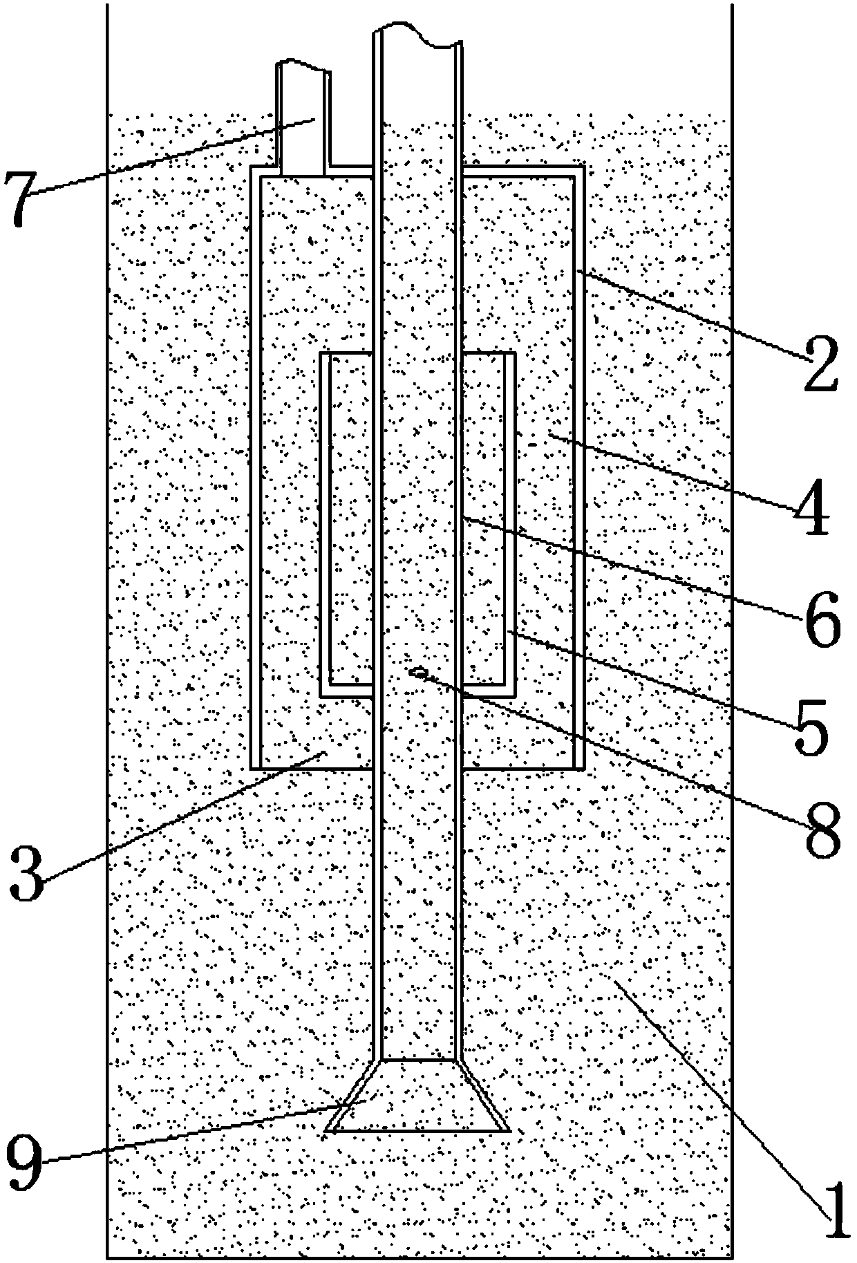
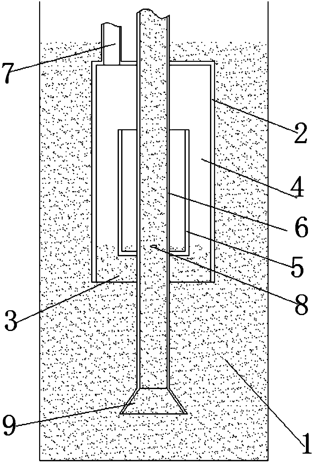
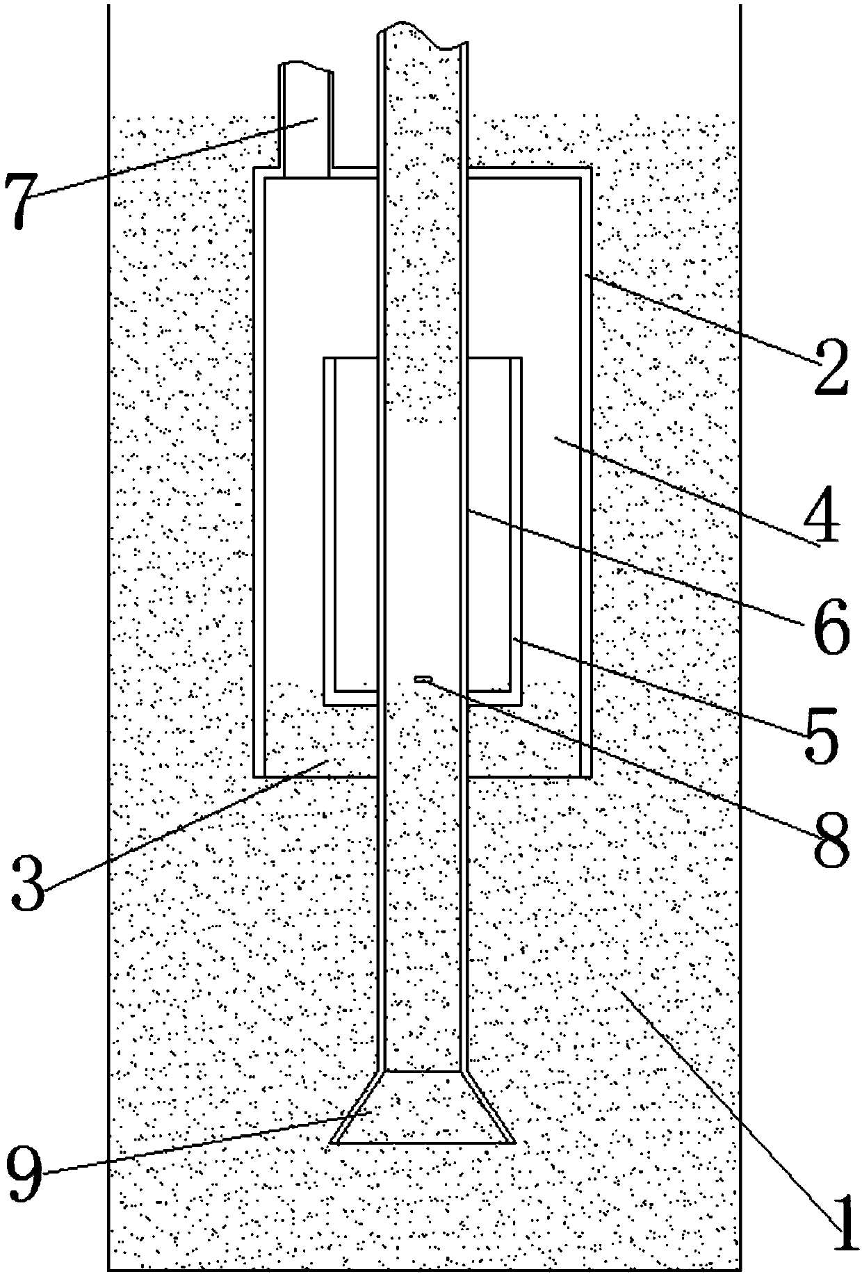
[0021] Such as figure 1 It is a schematic diagram of the structure of the non-electric pulse sewage lifting pump of the present invention before starting; the invention discloses a non-electric pulse sewage lifting pump, which includes a pump body 2 for setting below the liquid level of the sewage pool 1 and a pump body 2 protruding from the top of the sewage pool. The lift pipe 6 of the pool 1, the pump body 2 is provided with an atmospheric chamber 4 with an open bottom, a small air chamber 5 set in the large chamber 4 and with an open top, and the small air chamber 5 communicates with the large chamber 4 through the top opening, so The top of the pump body 2 is provided with an air inlet pipe 7 communicating with the large air chamber and the small air chamber, the riser 6 is set in the large air chamber 4 and the small air chamber 5 at ...


PUM


Abstract

The invention discloses a non-electric pulse type sewage lifting pump. The sewage lifting pump comprises a pump body and a lifting pipe, wherein the pump body is arranged below the liquid level of a sewage tank, and the top of the lifting pipe extends out of the sewage tank; the pump body is internally provided with a big air cavity with an opening at the bottom and a small air cavity with an opening at the top, wherein the small air cavity is arranged in the big air cavity in a sleeved mode, the small air cavity communicates with the big air cavity through the top opening, and the top of thepump body is provided with an air inlet pipe communicating with the big air cavity and the small air cavity; and the lifting pipe is arranged in the big air cavity and the small air cavity in a sleeved mode at the same time, the bottom of the lifting pipe extends out of the small air cavity to be provided with a water suction opening, and air inlet holes used for communicating with the small air cavity are formed in the pipe wall, located in the small air cavity, of the lifting pipe. According to the pump, the two air cavities of the big air cavity and the small air cavity are formed in the pump body, one of the two air cavities is placed upwards, the other air cavity is placed downwards, the small air cavity is arranged in the big air cavity, the lifting pipe penetrates through the middleof the two air cavities, and the air inlet holes are formed in the positions, close to the bottom of the small air cavity, of the lifting pipe; and continuous air inlet is adopted, bubbles are formedintermittently, the pollutant suction capacity is increased, and the lifting capacity is improved.

Description

technical field [0001] The invention belongs to the technical field of sewage treatment, in particular to a non-electric pulse sewage lifting pump. Background technique [0002] In the sewage treatment project, the sludge discharge problem of the sedimentation tank is a problem that people pay more attention to. At present, the sludge discharge device of the sedimentation tank is usually a submersible sewage pump, a conventional air lift device, etc.; but because the submersible sewage pump is installed underwater, this It brings a lot of inconvenience in installation, manufacture and maintenance; especially when the sedimentation tank is an inclined tube settler, since the inclined tube settler needs to cover the pool surface, when the submersible pump needs to be repaired and maintained, the inclined tube must be settled first It is very difficult to take out the device, and the construction is difficult; when the conventional air lift device is used, due to its structural...

Claims


Application Information

Patent Timeline
Patent Type & Authority Applications(China)
IPC IPC(8): F04D13/08F04D7/04F04D29/42F04D29/00
CPCF04D7/04F04D13/08F04D29/007F04D29/4293
Inventor 李渝
Owner 重庆林德科技发展有限公司
Why Eureka
Try Eureka