Underwater dirt suction device

A technology of sewage suction device and sewage plate, applied in fish farming, application, animal husbandry, etc., can solve the problem of insufficient suction of sewage suction device, and achieve the effect of improving sewage suction capacity and increasing suction force

Pending Publication Date: 2022-03-08
GUANGDONG OCEAN UNIVERSITY
View PDF3 Cites 0 Cited by
  • Summary
  • Abstract
  • Description
  • Claims
  • Application Information

AI Technical Summary

Problems solved by technology

[0004] Therefore, an underwater sewage suction device is provided to solve the problem of insufficient suction of existing sewage suction devices

Method used


Image

  • Underwater dirt suction device
  • Underwater dirt suction device
  • Underwater dirt suction device

Examples


Embodiment 1

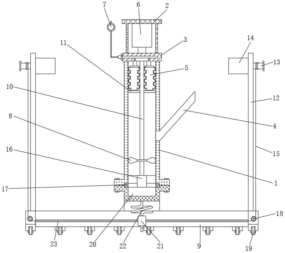
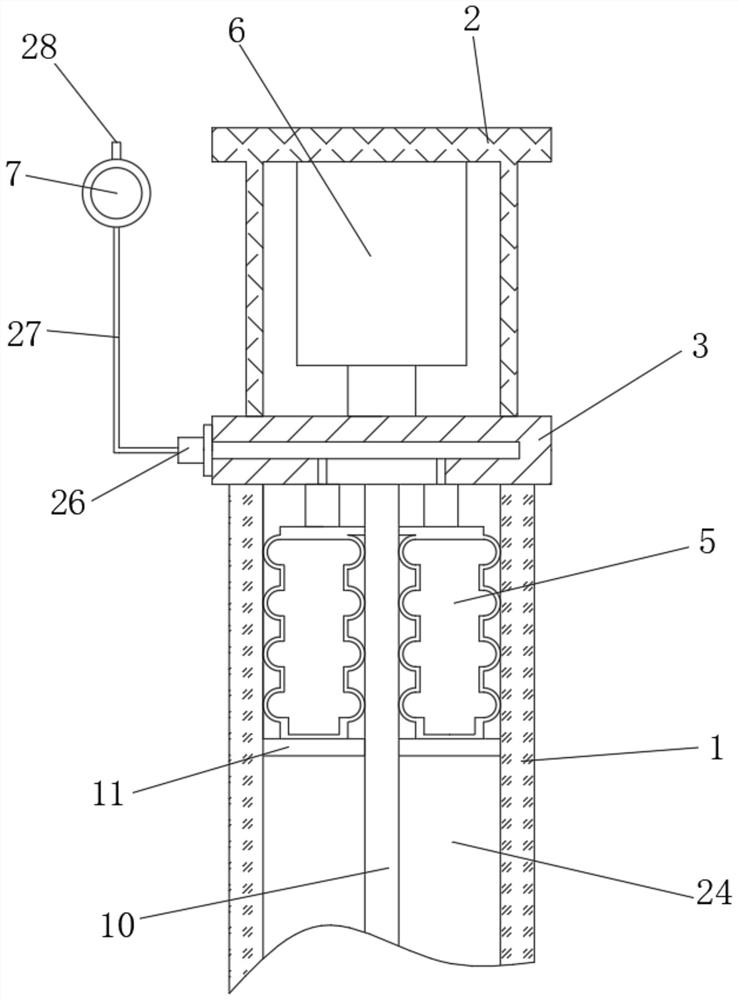
[0040] Example 1: In the initial stage of adsorption, the pressure-relieving airbag 5 is controlled to be in an inflated state by adjusting the ball 7, the pressure plate 11 is pressed down, and the air-releasing airbag 5 occupies most of the space at the upper end of the suction inner cavity 24, and the impeller 8 is driven by the brushless motor 6 Rotate to form a negative pressure suction to achieve the purpose of cleaning. At this time, the liquid level is above the lower end port of the discharge inclined tube 4, forming a sealed environment with the upper end inner wall of the sealing seat 3 and the dirt suction inner cavity 24.

[0041] By adjusting the cooperation of the ball 7 and the connecting valve 26, the pressure-relief air bag 5 is released, thereby increasing the volume of the sealed environment, reducing the pressure, and forming a negative pressure in the sealed environment, thereby increasing the suction force of the water flow and improving The adsorption fo...

Embodiment 2

[0042] Example 2: For the feces residual bait with strong adhesion, the feces residual bait sticks to the ground at the bottom of the pool, and it is difficult to clean it by adsorption.

[0043] Through the cooperation of the sleeve rod 23 and the sleeve 25, the horizontal sliding installation of the sliding beam 21 is realized, and the folding hose 22 is adapted to the lateral sliding position of the sliding beam 21 to maintain the connection with the water inlet pipe 1. The cooperation of the winding motor 14 and the winding roller 13 realizes pulling the stay cord 15, and then achieves the purpose of adjusting the lateral sliding position of the sliding crossbeam 21. Agitate, utilize the suction nozzle 30 to realize the adsorption and cleaning of the residual bait of the feces, so that the residual bait of the feces is stirred and scraped up, which is convenient to improve the efficiency of suction and the quality of cleaning.

Embodiment 3

[0044] Embodiment 3: For large-scale breeding farms, the breeding and cleaning area is relatively large, and the labor intensity of manual handling is relatively large.

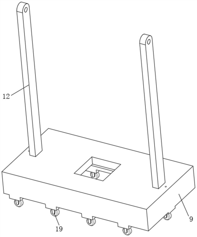
[0045] The convenient sliding of the dirt suction plate 9 is realized by setting the rollers 19, and the convenient movement of the dirt suction device is realized by the rollers 19, which is suitable for large-area adsorption cleaning.


PUM


Abstract

The invention relates to the technical field of underwater dirt suction devices, in particular to an underwater dirt suction device which comprises a dirt suction device body, the dirt suction device body comprises an axial flow pump and a dirt suction plate, and the axial flow pump comprises an impeller located in a water inlet pipe and driven by a brushless motor and a discharging inclined pipe obliquely communicated with the side wall of the water inlet pipe. The inner cavity of the water inlet pipe is internally provided with a pressure buffering air bag located above the lower end opening of the discharging inclined pipe, the pressure buffering air bag is externally connected with an adjusting ball capable of adjusting air pressure, and the lower end of the pressure buffering air bag is provided with a pressing plate installed on the inner wall of the water inlet pipe in a lifting mode. Under the driving adsorption of the motor, the water level in the water inlet pipe rises to the upper end of the discharging inclined pipe, a sealed environment is formed, then the pressure intensity of the pressure buffering air bag is adjusted through the adjusting ball, negative pressure is formed in the sealed environment, the water flow suction force is increased, and the sewage suction capacity is improved.

Description

technical field [0001] The invention relates to the technical field of underwater sewage suction devices, in particular to an underwater sewage suction device. Background technique [0002] The recirculating aquaculture system has limited treatment methods for residual bait and fecal particles, and the treatment effect has been unsatisfactory. The main problems are excessive investment scale, high energy consumption, and low economic benefits. [0003] The invention with the patent number CN202021133306.1 discloses a dual-purpose sewage suction device for sewage suction in swimming pools, which includes a connecting rod, a water outlet cover, a micro water pump and a sewage suction head. But the sewage sucker in this patent does not research micro water pump. The flow rate of ordinary water pumps is very small, the water flow velocity at the sewage suction head is weak, and the sewage suction effect is poor. There are more residual bait and feces at the bottom of the aquac...

Claims


Application Information

Patent Timeline
Patent Type & Authority Applications(China)
IPC IPC(8): A01K63/10A01K63/04
CPCA01K63/10A01K63/04
Inventor 袁剑平严谨巫炜杰蔡泽泓赖文川吴绵奎陈庆龙
Owner GUANGDONG OCEAN UNIVERSITY
Why Eureka
Try Eureka