
Spherical parachute

A parachute and spherical technology, applied in the field of parachutes, can solve the problems of over-inflation of the parachute, harsh design conditions of the parachute, serious breathing problems, etc., and achieve the effects of increasing air resistance, improving the deceleration effect and working stability.

Pending Publication Date: 2018-02-02
XIANGYANG HONGWEI AIRCRAFT
View PDF10 Cites 0 Cited by
  • Summary
  • Abstract
  • Description
  • Claims
  • Application Information

AI Technical Summary

Problems solved by technology

In the above-mentioned application environment, the application of traditional fabric parachutes is greatly restricted, and it has many structural defects and cannot be effectively applied. For example, in the case of high altitude and / or high Mach, the traditional fabric parachute may be The dynamic pressure is too low so that the parachute cannot be fully filled, and further causes the parachute to be entangled, so that the parachute cannot be fully filled when the dynamic pressure increases in the late stage of parachute opening, which affects the normal use of the parachute; Applications in sonic and / or hypersonic environments also have the problem of canopy breathing, that is, the canopy will sometimes be over-inflated, sometimes completely collapsed, or some abnormal state in between these two limit states, and the traditional fabric parachute The "breathing" rate of the aircraft is very high, which makes the breathing problem more serious; in addition, in the case of low altitude and high Mach, the parachute must be able to withstand large structural loads, which makes the design conditions of the parachute more stringent

Method used


Image

  • Spherical parachute
  • Spherical parachute
  • Spherical parachute

Examples


Embodiment Construction

[0031] In order to make the object, technical solution and advantages of the present invention clearer, the present invention will be further described in detail below in conjunction with the accompanying drawings and embodiments. It should be understood that the specific embodiments described here are only used to explain the present invention, not to limit the present invention.

[0032] In addition, the technical features involved in the various embodiments of the present invention described below can be combined with each other as long as they do not constitute a conflict with each other.

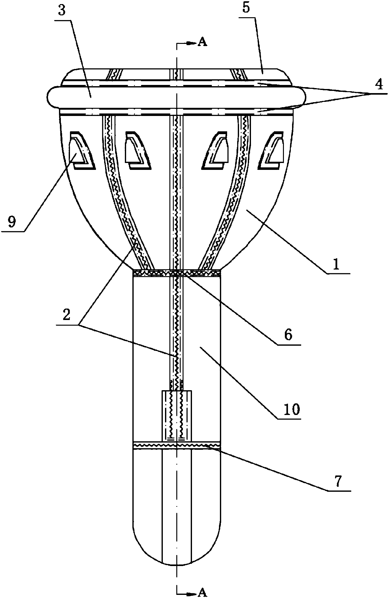
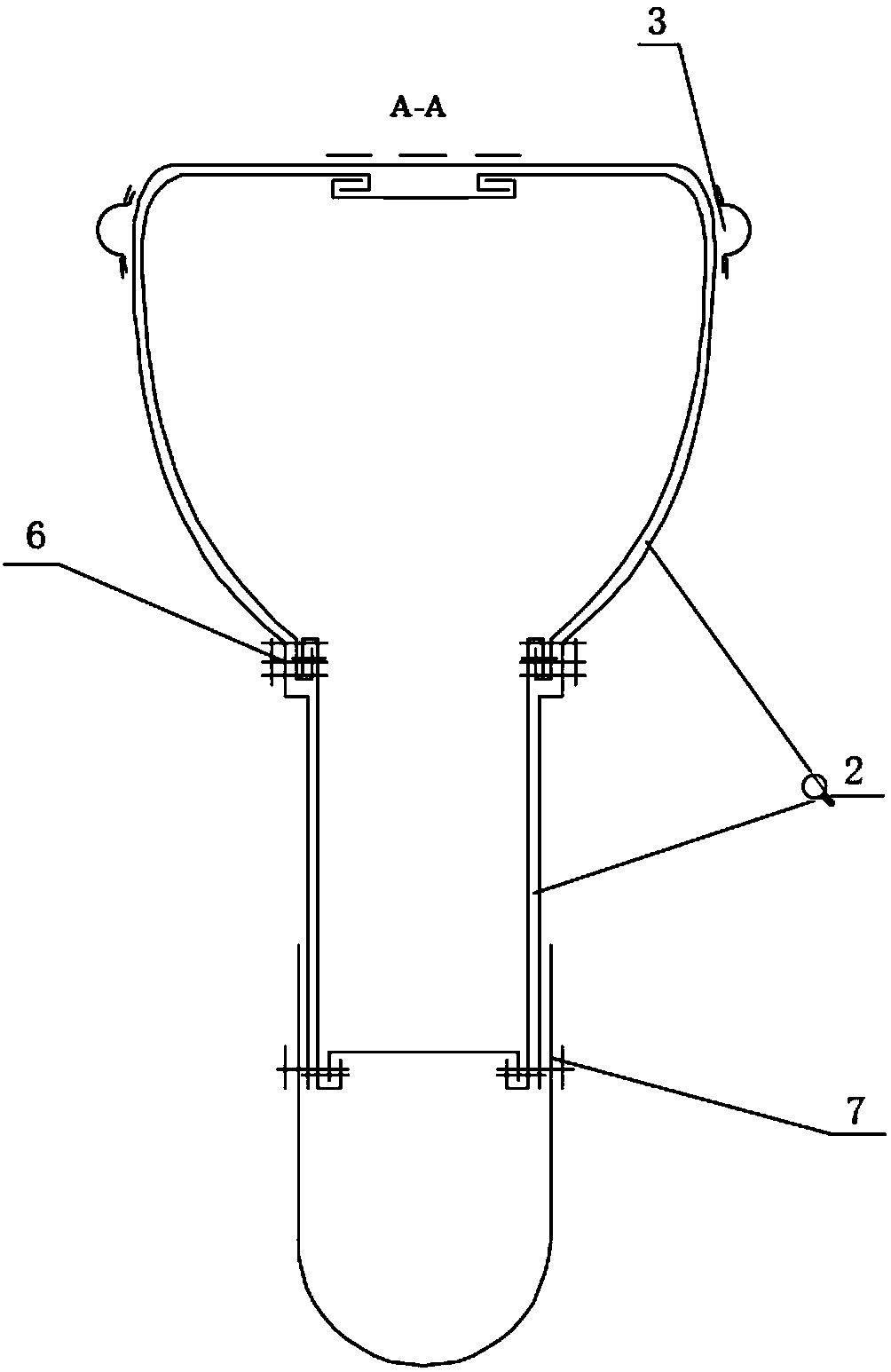
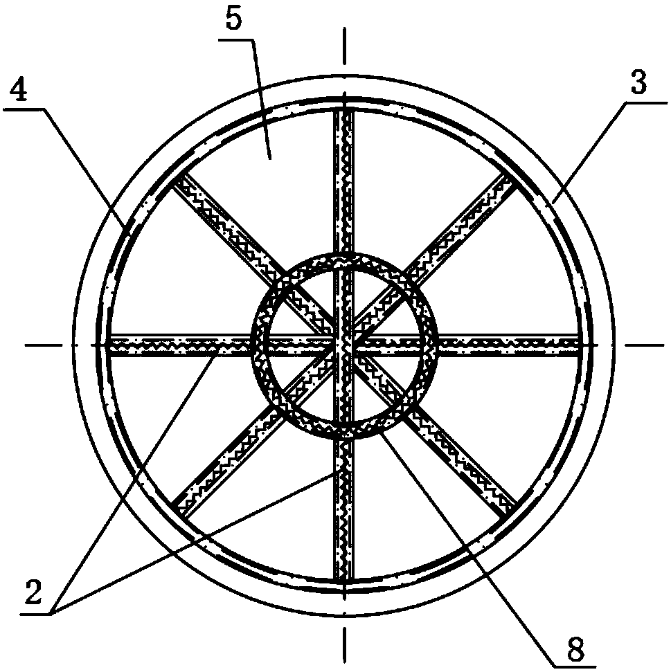
[0033] The spherical parachute in the preferred embodiment of the present invention is as Figure 1~5 As shown, among them, figure 1 It is a schematic diagram of the overall structure of the spherical parachute in the first embodiment of the present invention; figure 2 It is the A-A sectional view of the overall structure of the spherical parachute in the first embodiment of the pres...


PUM


Abstract

The invention discloses a spherical parachute, and belongs to the relevant technical field of parachutes. The spherical parachute comprises a parachute main body and a parachute front-loading body, wherein the top of the parachute main body is sealed; the parachute main body is formed by splicing of a parachute body and a parachute top; the parachute front-loading body is connected to the lower part of the parachute body, is used for connecting an article to be carried, and is formed by splicing of parachute gores, a top gore and a bottom gore; an air inlet allowing ram air to enter is formedin each parachute gore; and a turbulence ring is arranged at the top of the parachute body. According to the spherical parachute disclosed by the invention, the surfaces of the parachute gores in a revert inverted cone shape are used as a pneumatic resistance surface, so that the pressure difference resistance and frictional resistance are generated, the application of the parachute in a supersonic environment or a hypersonic environment is effectively realized, the problem of "breathing" existing in a conventional parachute is solved, and the spherical parachute can be effectively suitable for the application in a supersonic environment or a hypersonic environment, simple in structure and high in stability.

Description

technical field [0001] The invention belongs to the technical field related to parachutes, and in particular relates to a spherical parachute. Background technique [0002] Parachute is a kind of expandable aerodynamic reducer that utilizes the principle of air resistance and relies on inflation relative to air movement. With the continuous development of parachute technology, the application fields of parachute are becoming wider and wider. It has been widely used in the fields of airborne airdrop, air deceleration, emergency rescue and aircraft recovery. And / or hypersonic aviation or military applications are also increasingly required. [0003] The supersonic environment refers to the movement of the items carried by the parachute at a speed exceeding the speed of sound, while the hypersonic environment refers to the movement of the items carried by the parachute at a speed exceeding 5 times the speed of sound. The above two application environments often appear in the f...

Claims


Application Information

Patent Timeline
Patent Type & Authority Applications(China)
IPC IPC(8): B64D17/02B64D17/62B64D17/30
CPCB64D17/02B64D17/30B64D17/62
Inventor 张正宇徐志修李小鹏郭炳磊李翀
Owner XIANGYANG HONGWEI AIRCRAFT
Learn More