Electromechanical drive architecture and braking force control method for redundant electric brakes

A technology of brake control and drive control, applied in the direction of control mechanism, aircraft braking arrangement, brake, etc., can solve problems such as the deterioration of the force condition of the landing gear, the reduction of the braking ability of the aircraft, the loss of braking ability, etc., and achieve basic balance and heading stability. , High safety, the effect of ensuring brake safety

Active Publication Date: 2020-05-19
XIAN AVIATION BRAKE TECH
View PDF3 Cites 0 Cited by
  • Summary
  • Abstract
  • Description
  • Claims
  • Application Information

AI Technical Summary

Problems solved by technology

[0007] In order to overcome the problem existing in the prior art that when the electromechanical drive fails, the electromechanical actuators on some wheel brake devices will completely lose the braking ability, resulting in a reduction in the braking ability of the aircraft, or the brake will deviate, so that it will rush out of the runway , deviation from the runway, and deterioration of the stress on the landing gear, the present invention proposes a redundant electric brake electromechanical drive structure and a braking force control method.

Method used


Image

  • Electromechanical drive architecture and braking force control method for redundant electric brakes
  • Electromechanical drive architecture and braking force control method for redundant electric brakes
  • Electromechanical drive architecture and braking force control method for redundant electric brakes

Examples


Embodiment 1

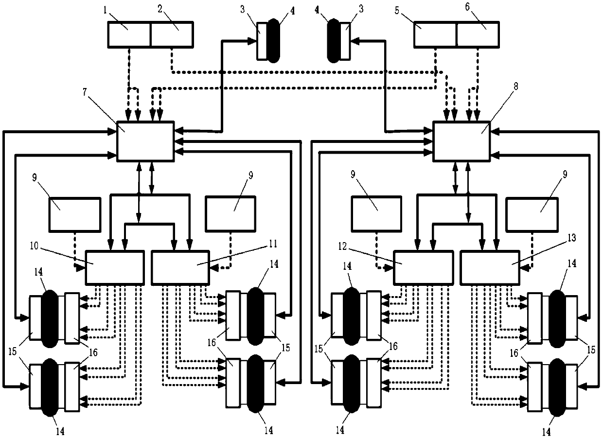
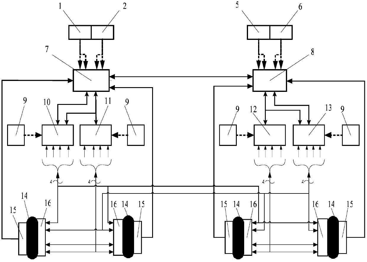
[0050] This embodiment is the electric brake control and monitoring system that is built as the target machine with four main wheels aircraft, as figure 2shown. The working principle of the aircraft electric brake control and monitoring system is the same as that of the B757 aircraft, except that a redundant electric brake electromechanical drive structure is adopted, so that multiple electromechanical actuators on each main brake wheel are controlled by different electromechanical drivers , its main feature is that: the left and right sides of the aircraft are respectively equipped with two electromechanical drivers, each electromechanical driver has four control channels to generate four driving signals to the electromechanical actuators, the first electromechanical driver controls each main brake One electromechanical actuator on the wheel, the second electromechanical drive controls the two main brakes on the left main landing gear Two electromechanical actuators on each ...

Embodiment 2

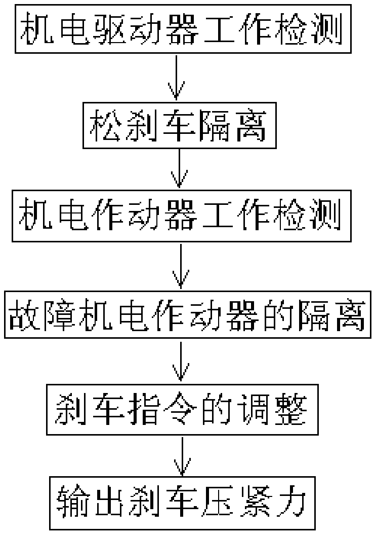
[0065] This embodiment is a braking force control method for the redundant electric brake electromechanical drive framework of the present invention when the electric brake power supply unit, the electromechanical driver and the electromechanical actuator fail. The specific process is:


PUM


Abstract

Provided are a redundant electric braking electromechanical-driven framework and a braking force control method. A typical electric braking and monitoring system is established with an airplane with four main braking wheels as a target machine, a plurality of electromechanical actuators on each main braking wheel are controlled by different electromechanical drivers, when certain channels are broken down, the braking capacity of the airplane is maintained to the greatest extent by increasing the braking compression force output by the normal electromechanical drivers, the task reliability of the airplane in the landing braking process is enhanced, meanwhile, severe unbalance of the braking torques of the two sides of the airplane is avoided, the airplane is prevented from drifting of a runway, deformation of an undercarriage under asymmetrical braking loads is reduced, and the working environment of a braking system is improved; and meanwhile, the braking distance is shortened, the safety of the airplane in case of failure of the electric braking system is further improved, the possibility that the airplane suffers braking failure under various complex combined failure states can be reduced, and the braking capacity of the airplane is improved to the greatest extent.

Description

technical field [0001] The invention belongs to the field of electromechanical actuator control in aircraft brake system engineering, and in particular relates to the improvement of the electromechanical drive structure of aircraft electric brakes. Background technique [0002] The aircraft electric braking system uses electric energy as a power source to control the braking force acting on the aircraft wheels according to the braking command imposed by the pilot. [0003] Boeing's B787 aircraft is currently the most advanced electric brake system, using electromechanical actuation and drive control technology. figure 1 It is the structural principle diagram of the brake control and monitoring system of B787 aircraft, mainly including one captain left brake command sensor 1 and one captain right brake command sensor 2, two front wheel remote data concentrators 3 and two front wheel 4, One chief pilot left brake command sensor 5 and one chief pilot right brake command sensor...

Claims


Application Information

Patent Timeline
Patent Type & Authority Patents(China)
IPC IPC(8): B64C25/44B60T13/74
CPCB60T13/74B64C25/44
Inventor 张谦张颖姝
Owner XIAN AVIATION BRAKE TECH
Why Eureka
Try Eureka