
Clamping device for machining small eccentric stepped circular hole parts

A technology of clamping device and small eccentricity, which is applied in the direction of metal processing machinery parts, positioning devices, metal processing equipment, etc., can solve the problems of meeting the requirements of size and position relationship, increasing the cost of clamping device, consuming processing time, etc., and achieving improvement The effects of processing accuracy, reducing the burden on the warehouse, and improving processing efficiency

Inactive Publication Date: 2018-02-02
CHENGDU ENGINE GROUP
View PDF4 Cites 1 Cited by
  • Summary
  • Abstract
  • Description
  • Claims
  • Application Information

AI Technical Summary

Problems solved by technology

The processing of this kind of parts requires several sets of clamping devices in the prior art, and the processing is carried out in different steps. Therefore, the parts need to be repeatedly positioned during the processing, resulting in large errors. High, and several processes are processed, and the clamping of the clamping device also consumes a lot of processing time, which affects the processing efficiency. The production of several sets of clamping devices will inevitably increase the cost of the clamping device

Method used


Image

  • Clamping device for machining small eccentric stepped circular hole parts
  • Clamping device for machining small eccentric stepped circular hole parts
  • Clamping device for machining small eccentric stepped circular hole parts

Examples


Embodiment Construction

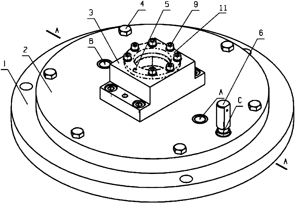
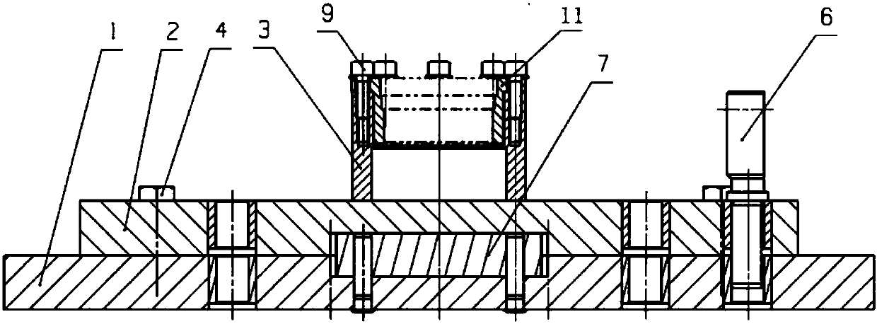
[0021] The clamping device and usage method for processing small eccentric stepped round hole parts according to the present invention will be further described below through examples and in conjunction with the accompanying drawings.

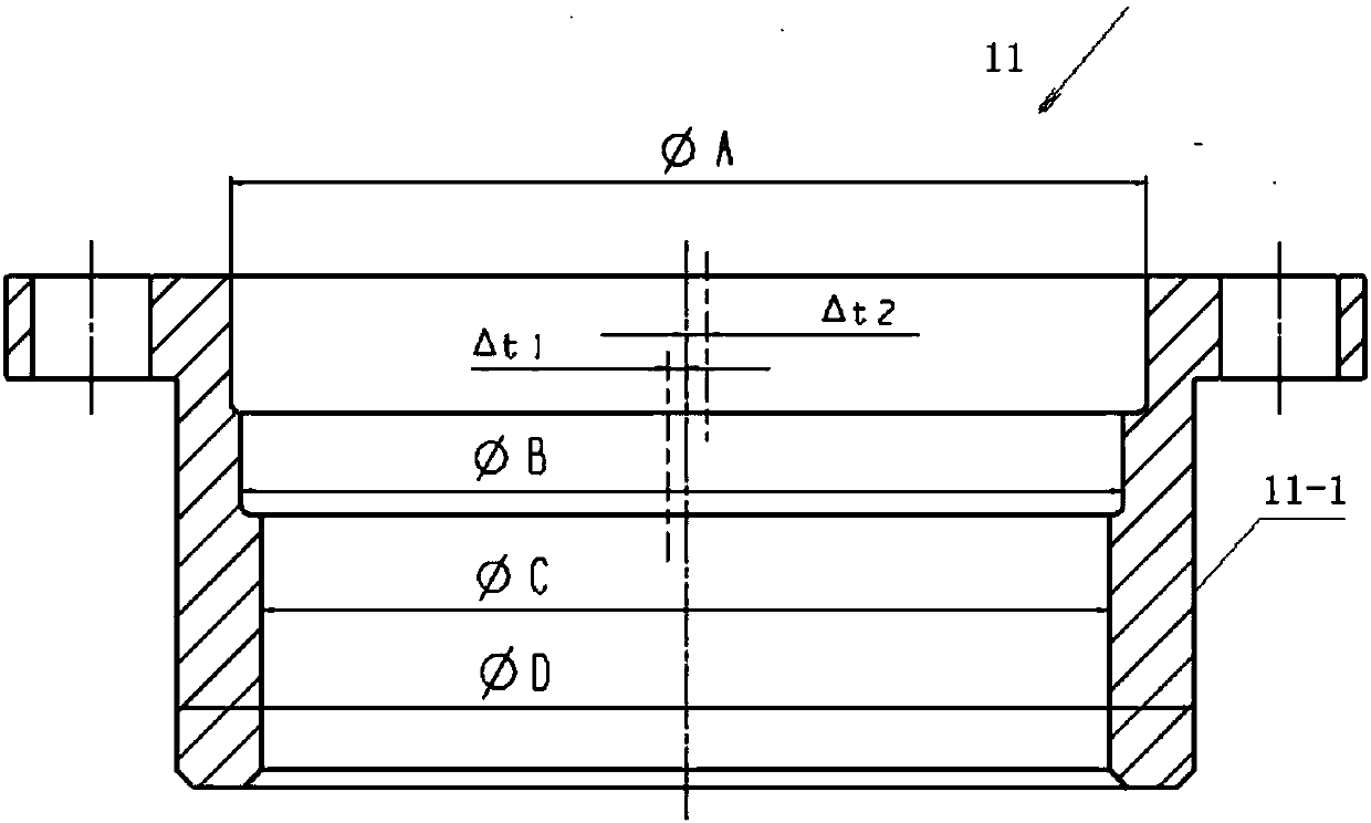
[0022] The clamping device described in this embodiment is used for figure 1 The processing of the small eccentric stepped round hole parts shown is from figure 1 It can be seen that in this part, the centerline of the circular hole with the lower aperture of ΦC is on a straight line with the centerline of the positioning outer cylindrical surface 1-1, which is a non-eccentric hole, and the centerline of the circular hole with the upper and middle aperture of ΦB is located at the positioning On the left side of the center line of the outer cylindrical surface 1-1, the eccentric distance △t1=0.2mm, the center line of the circular hole with the upper aperture diameter ΦA is located on the right side of the center line of the outer cylindrical sur...


PUM


Abstract

The invention discloses a clamping device for machining small eccentric stepped circular hole parts. The device comprises a base, an indexing plate, a positioning base, an indexing guide plate, an indexing bolt and indexing adjusting mechanisms, wherein the indexing guide plate is a rectangular plate body; the base is in a circular truncated cone shape; a first groove used for installing the indexing guide plate is formed in the top surface of a top seat; a first indexing bolt hole is formed in the base; the indexing plate is in a circular truncated cone shape; a second groove which is combined with the indexing guide plate is formed in the bottom surface of the indexing plate; a second indexing bolt hole is formed in the indexing plate; the positioning seat is provided with a central holewhich is combined with the small eccentric stepped round hole parts to be machined; the indexing guide plate is fixed in the first groove formed in the top surface of the base; the positioning seat is fixed on the top surface of the indexing plate; a second groove formed in the bottom surface of the indexing plate is combined with the indexing guide plate, and the indexing plate is located on thetop surface of the base; the indexing bolt is inserted into one certain second indexing bolt hole in the indexing plate and a first indexing bolt hole corresponding to the second indexing bolt hole;and the various indexing adjusting mechanisms are used for fixedly connecting the base with the indexing plate.

Description

technical field [0001] The invention belongs to the field of fixtures used in parts machining, in particular to a clamping device for machining small eccentric stepped round hole parts. Background technique [0002] The small eccentric stepped hole part means that the eccentricity of the stepped hole of the part relative to the positioning outer cylindrical surface is not greater than 1mm. The processing of this kind of parts requires several sets of clamping devices in the prior art, and the processing is carried out in different steps. Therefore, the parts need to be repeatedly positioned during the processing, resulting in large errors. High, and several processes are processed, and the clamping of the clamping device also consumes a lot of processing time, which affects the processing efficiency. The manufacture of several sets of clamping devices will inevitably increase the cost of the clamping device. Therefore, how to ensure that the size and positional relationship...

Claims


Application Information

Patent Timeline
Patent Type & Authority Applications(China)
IPC IPC(8): B23Q3/06
CPCB23Q3/062
Inventor 罗仁俊周健飞王均李亚肖国郁
Owner CHENGDU ENGINE GROUP
Learn More