
Intelligent multifunctional cabinet

A multi-functional, cabinet technology, applied in cabinets, kitchen cabinets, legs of general furniture, etc., can solve the problems of reducing the use effect, difficult to place kitchen utensils, occupying a large space, etc., to strengthen the fixing strength, enhance the use effect, and facilitate the use of moving effect

Pending Publication Date: 2018-01-26
汇森家具(龙南)有限公司
View PDF0 Cites 3 Cited by
  • Summary
  • Abstract
  • Description
  • Claims
  • Application Information

AI Technical Summary

Problems solved by technology

[0002] In the prior art, with the continuous improvement of people's living standards, people have higher and higher requirements for kitchen equipment, and more and more kitchen utensils have entered ordinary families, but most of these kitchen utensils are products with single functions, and the kitchen area Limited, difficult to place various kitchen utensils
For example, soymilk machines, tofu machines, sprouting machines, dishwashers, disinfection cabinets and cupboards are commonly used equipment in the kitchen, and these devices are often placed separately. Although they have their own functions, due to the scattered distribution It takes up a lot of space, is inconvenient to operate, and is not beautiful, which brings a lot of inconvenience to family life.
[0003] Existing multifunctional cabinets do not have a gas stove protection device. When the gas stove is not used for a long time, dust is easy to accumulate on the gas stove, which is not easy to clean. The drawers of the existing multifunctional cabinet cannot automatically expand and contract. You need to bend down to pull out the drawer, which is inconvenient to use and reduces the use effect. The existing multi-functional cabinet has no mobile device, which is not easy to carry, and it is time-consuming and labor-intensive to carry

Method used


Image

  • Intelligent multifunctional cabinet
  • Intelligent multifunctional cabinet
  • Intelligent multifunctional cabinet

Examples


specific Embodiment approach

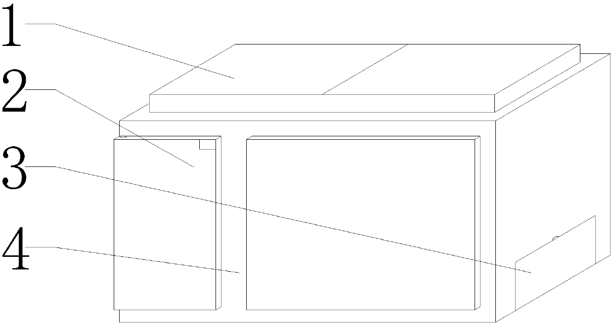
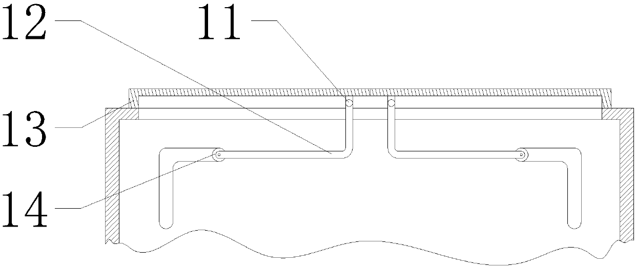
[0027]Specific implementation method: when the staff needs to use the gas stove, the staff holds the outer end of the protective cover 13, and then the staff moves the protective cover 13 outwards, because the L-shaped support rod 12 is installed on the front and rear ends of the hanging rod 11, and the hanging rod 11 is arranged on the upper side of the main body 4, and the sliding wheel 14 is installed on the outer end of the L-shaped support rod 12, and the sliding wheel 14 is connected with the L-shaped support rod 12 through the rotating shaft, so the outward movement of the protective cover 13 drives the outward movement of the sliding wheel 14 , when the protective cover 13 is moved to a proper position, the staff rotates the protective cover 13 around the sliding wheel 14, and the rotation of the protective cover 13 drives the L-shaped support rod 12 to rotate. When the protective cover 13 is rotated to a suitable position, the staff moves down Protective cover 13, the ...


PUM


Abstract

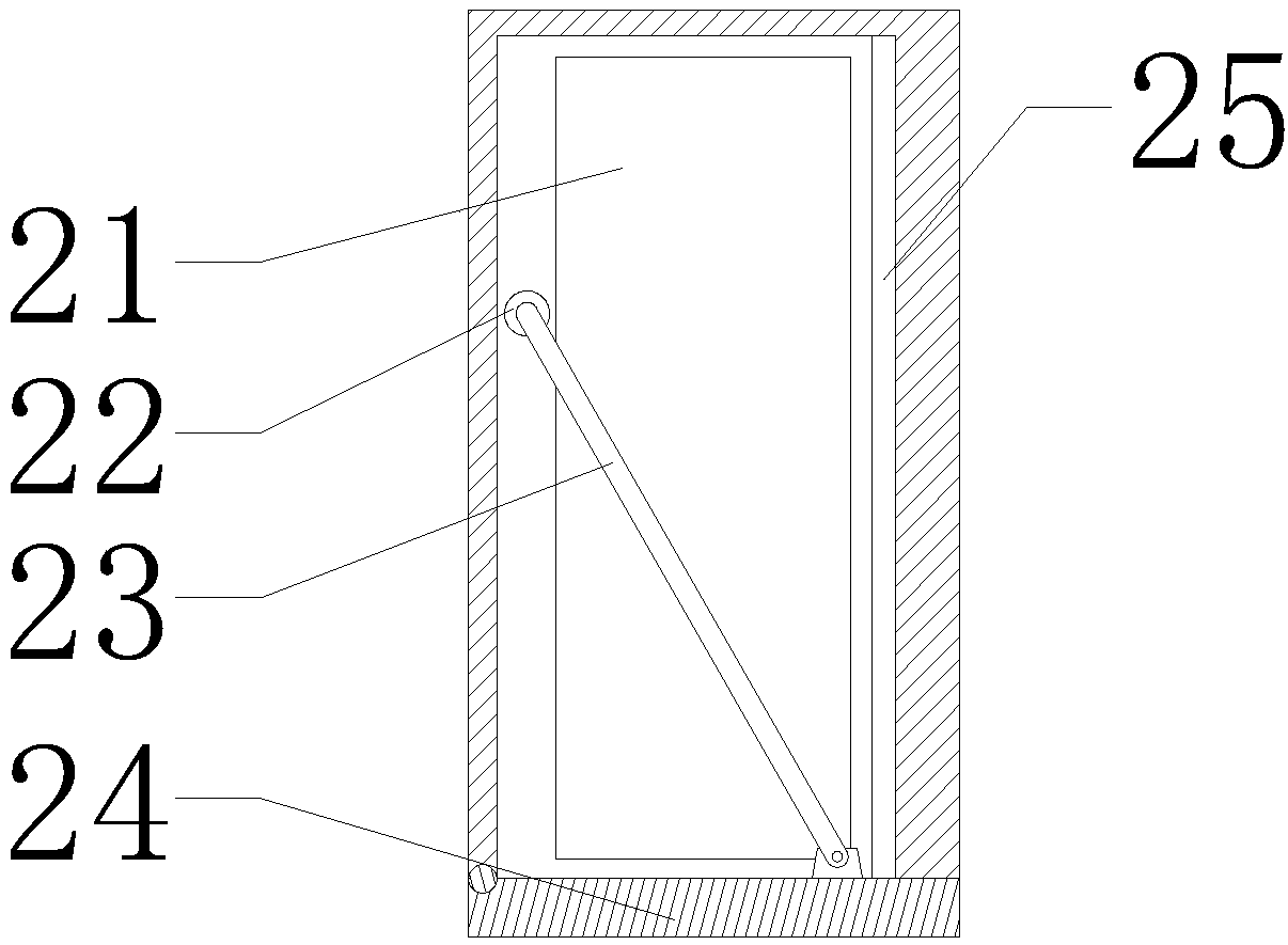
The invention provides an intelligent multifunctional cabinet. The intelligent multifunctional cabinet comprises hanging rods, L-shaped supporting rods, a protective cover, slide wheels, a drawer, a round rod, a rotating rod, a cabinet door and a draw slip. The protective cover is mounted at the upper ends of the L-shaped supporting rods and is fixed on the upper sides of the hanging rods, the L-shaped supporting rods are mounted at the outer ends of the hanging rods, and the slide wheels are mounted at the outer ends of the L-shaped supporting rods, so that a gas stove can be protected. The round rod is arranged on the drawer, the rotating rod is arranged at the upper end of the round rod, fixed on the upper side of the drawer and mounted at the rear end of the cabinet door, the cabinet door is mounted at the front end of the drawer and arranged at the front end of the draw slip, and the draw slip is mounted at the right end of the drawer, so that the drawer can be driven to extend out when the cabinet door is opened, and further can be retracted automatically. The intelligent multifunctional cabinet is convenient to use, move and clean and highly reliable.

Description

technical field [0001] The invention is an intelligent multifunctional cabinet, which belongs to the technical field of intelligent home furnishing. Background technique [0002] In the prior art, with the continuous improvement of people's living standards, people have higher and higher requirements for kitchen equipment, and more and more kitchen utensils have entered ordinary families, but most of these kitchen utensils are products with single functions, and the kitchen area Limited, it is difficult to place various kitchen utensils. For example, soymilk machines, tofu machines, sprouting machines, dishwashers, disinfection cabinets and cupboards are commonly used equipment in the kitchen, and these equipment are often placed separately. Although they have their own functions, due to the scattered distribution The disadvantages of taking up a large space, inconvenient operation, and unsightly appearance bring a lot of inconvenience to family life. [0003] Existing mul...

Claims


Application Information

Patent Timeline
Patent Type & Authority Applications(China)
IPC IPC(8): A47B77/08A47B77/02A47B96/00A47B88/453A47B91/02A47B91/06
Inventor 曾明
Owner 汇森家具(龙南)有限公司
Learn More