
Wireless charging circuit, wireless charging system and circuit control method

A wireless charging and circuit technology, applied in battery circuit devices, transmission systems, circuit devices, etc., can solve problems such as limited impact resistance, increased circuit cost and volume, and low efficiency

Inactive Publication Date: 2018-01-23
HUAWEI TECH CO LTD
View PDF2 Cites 15 Cited by
  • Summary
  • Abstract
  • Description
  • Claims
  • Application Information

AI Technical Summary

Problems solved by technology

[0004] In the above method of adjusting output power, if a power electronic device is used as a controllable switch to adjust the capacitor, there will be problems of large conduction loss and low efficiency. If a relay is used as a controllable switch to adjust the capacitor, there will be a problem of limited impact resistance , relying on the mechanical structure to adjust the inductance also increases the cost and volume of the circuit. In addition, in the above method of adjusting the output power, an additional circuit is added in the system to achieve the purpose of adjusting the output power, which not only increases the cost and volume of the circuit, but also reduces System Efficiency and Power Density

Method used


Image

  • Wireless charging circuit, wireless charging system and circuit control method
  • Wireless charging circuit, wireless charging system and circuit control method
  • Wireless charging circuit, wireless charging system and circuit control method

Examples


Embodiment Construction

[0045] In order to make the object, technical solution and advantages of the present invention clearer, the implementation manner of the present invention will be further described in detail below in conjunction with the accompanying drawings.

[0046] The "module" mentioned in this article refers to the program or instruction that can realize certain functions stored in the memory; the "unit" mentioned in this article refers to a functional structure divided according to logic, and the "unit" can be composed of Pure hardware implementation, or a combination of software and hardware.

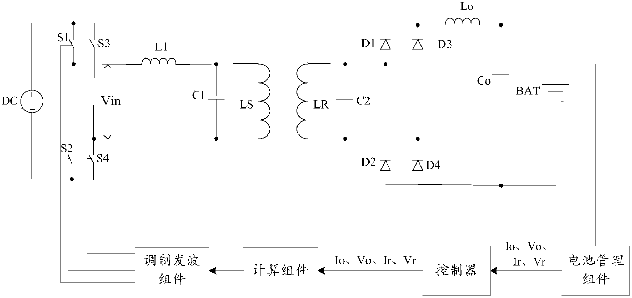
[0047] Please refer to figure 1 , which shows a schematic structural diagram of an exemplary wireless charging system provided by the present invention, the wireless charging system includes a power supply 100, a transmitting end 110 connected to the power supply, a receiving end 120, a battery assembly 130 connected to the receiving end 120, and The battery assembly 130 is connected to the bat...


PUM


Abstract

The invention discloses a wireless charging circuit, a wireless charging system and a circuit control method, and belongs to the technical field of wireless charging. The wireless charging circuit comprises a DC / AC converter, a wireless transmitter, a control component and a wireless communication component. The wireless communication component is used for receiving the charging parameters fed back by a receiving side. The control component is used for transmitting a first driving signal or a second driving signal to the DC / AC conversion module according to the charging parameters. The DC / AC converter is used for being in the work state under the control of the first driving signal and converting the DC voltage in the work state and being in the work stop state under the control of the second driving signal and performing no conversion of the DC voltage in the work stop state. The problem of increasing of the circuit cost and the size of the present output power adjustment method can be solved so that the effects that the average power of the actual load of the receiving side is enabled to be equal to or close to the needed power of the load and the efficiency and the power densityof the wireless charging system can be enhanced can be achieved.

Description

technical field [0001] The invention relates to the technical field of wireless charging, in particular to a wireless charging circuit, a wireless charging system and a circuit control method. Background technique [0002] Wireless charging means that the receiving end with a battery obtains power from the transmitting end through electromagnetic wave induction, wherein the transmitting end generates an electromagnetic signal, and the receiving end senses the electromagnetic signal to generate current to charge the battery. [0003] Since the capacity of the battery to be charged is different, it is necessary to adjust the output power of the transmitting end and the receiving end according to the load. In the commonly used method of adjusting the output power, the impedance matching circuit is added at the transmitting end and the receiving end respectively, the capacitance is adjusted by the adjustable capacitor in the impedance matching circuit, and the inductance is adju...

Claims


Application Information

Patent Timeline
IPC IPC(8): H02J7/00H02J50/10
CPCH02J50/80H02J50/12H02J7/04H02J7/00714H02J7/007182H04B5/72H04B5/79
Inventor 毛云鹤
Owner HUAWEI TECH CO LTD
Learn More