Broadband mimo antenna based on four elements

A four-element, antenna technology, applied in the field of broadband MIMO antennas, can solve the problems of narrow MIMO antenna bandwidth, low channel capacity, and large overall size of the antenna, and overcome the characteristics of narrow impedance bandwidth, high isolation, and large size Effect

Active Publication Date: 2019-07-16
XIDIAN UNIV +1
View PDF2 Cites 0 Cited by
  • Summary
  • Abstract
  • Description
  • Claims
  • Application Information

AI Technical Summary

Problems solved by technology

[0004] In 2016, Shen Dongya of Yunnan University and others invented a 4×4 ultra-wideband MIMO antenna, the patent application publication number is CN106532235A, in which the antenna is composed of a radiation unit, a feeder line and a ground plate, and the dielectric substrate adopts a dielectric constant of 4.4 , FR4 with a loss tangent of 0.02, with a size of 60mm×60mm×1.6mm. By introducing two symmetrical rectangular mesh cross-type isolation structures, the antenna has obtained good isolation performance, but the overall size of the antenna is relatively large , not conducive to installation in terminal equipment
[0005] In 2017, Wu Yanjie and others from Guangdong University of Technology invented a compact high-isolation MIMO antenna. The patent application publication number is CN106374212A. The antenna unit is composed of a radiation unit, a feeder line and a ground plate, and the dielectric substrate is FR4. Polarization diversity and pattern diversity are achieved through the placement of the first unit and the second unit of the antenna to achieve high isolation, but the number of antenna units is 2, resulting in a low channel capacity of the system, which cannot meet the speed requirements of today's communications
[0006] In 2014, Wu Yuting and others from the Seventh Research Institute of China Electronics Technology Group Corporation invented a four-element broadband slot MIMO antenna without decoupling structure. The patent application publication number is CN1O4638365A. The adjacent antenna elements are perpendicular to each other, and no decoupling structure is introduced. It can also obtain high isolation characteristics, but its operating bandwidth is relatively narrow, which cannot meet the needs of the next generation of mobile communications.
[0007] In summary, the currently reported MIMO antennas usually have very narrow bandwidth, relatively low isolation, and relatively large size, while the channel capacity of the two-element MIMO antenna system is usually very low, which cannot meet the needs of the next generation communication system.

Method used


Image

  • Broadband mimo antenna based on four elements
  • Broadband mimo antenna based on four elements
  • Broadband mimo antenna based on four elements

Examples


Embodiment 1

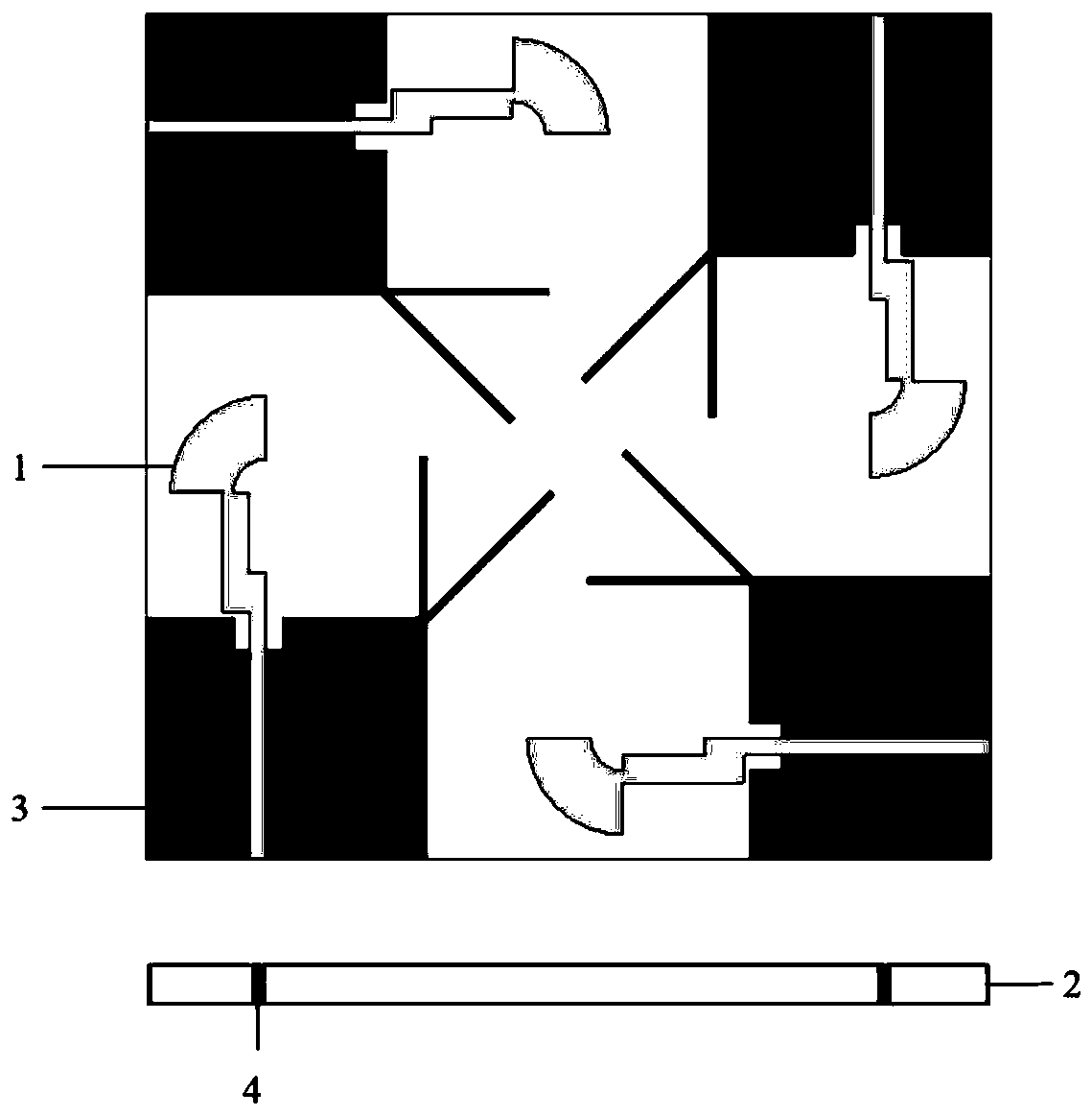
[0028] refer to figure 1 , the present invention includes a radiation layer 1, a dielectric substrate 2, a metal floor 3 and a feed port 4, wherein the radiation layer 1 is arranged on the upper surface of the dielectric substrate 2, and the metal floor 3 is arranged on the lower surface of the dielectric substrate 2. The radiation layer 1 and the metal floor 3 are rotationally symmetrical to the center of the dielectric substrate 2 .

[0029] refer to figure 2 , the MIMO antenna unit in the present invention includes a radiation unit 11 , a defective branch compound structure and a feeder port 41 .

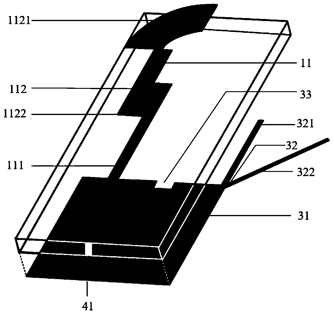
[0030] The radiating unit 11 is composed of a feeder 111 and a monopole 112 , the feeder 111 is located on one side of the edge of the upper surface of the dielectric substrate 2 , and the monopole 112 is arranged at the edge directly above the radiating unit 11 .

[0031] The monopole 112 is composed of a fan-shaped metal patch 1121 and an "L"-shaped metal patch 1122. The fan...

Embodiment 2

[0041] This embodiment has the same structure as Embodiment 1, only the following parameters are adjusted:

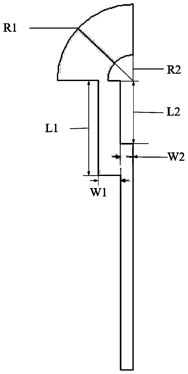
[0042] refer to image 3 , the fan-shaped metal patch 1121 has an outer radius R1 of 5mm and an inner radius R2 of 1.5mm.

[0043] The length W1 of the outer side of the "L"-shaped metal patch 1122 is 6.0 mm, the width L1 is 1.5 mm, the length L2 of the inner side is 4.0 mm, and the width W2 is 0.5 mm.

[0044]refer to Figure 4 , the length L3 of the first branch 321 is 10 mm, the length L4 of the second branch 322 is 13 mm, and the angle α between the two branches is 30°.

Embodiment 3

[0046] This embodiment has the same structure as Embodiment 1, only the following parameters are adjusted:

[0047] refer to image 3 , the fan-shaped metal patch 1121 has an outer radius R1 of 7mm and an inner radius R2 of 2.5mm.

[0048] The length W1 of the outer side of the "L"-shaped metal patch 1122 is 9.0 mm, the width L1 is 2.5 mm, the length L2 of the inner side is 6.0 mm, and the width W2 is 1.5 mm.

[0049] refer to Figure 4 , the length L3 of the first branch 321 is 12 mm, the length L4 of the second branch 322 is 15 mm, and the angle α between the two branches is 50°.

[0050] Effect of the present invention will be further described below in conjunction with accompanying drawing:

[0051] Simulation 1, the present invention simulates the MIMO antenna unit model in Embodiment 1 in the frequency band 3.0GHz-4.0GHz through the modeling of electromagnetic simulation software Ansoft HFSS, and the obtained S11 curve is as follows Figure 5 shown, where Figure 5 ...


PUM


Abstract

The invention discloses a broadband MIMO antenna based on four units, and mainly aims to solve the problem that the existing MIMO antenna features narrow band, large size and low channel capacity. Thebroadband MIMO antenna includes a dielectric substrate (2), a metal floor (3), and a feed port (4). A radiation layer (1) is arranged on the surface of the dielectric substrate. The radiation layer includes four identical radiation units (11) distributed symmetrically. Each radiation unit includes a feeder (111) and a monopole (112). Each monopole is composed of a fan-shaped metal patch (1121) and an 'L'-shaped metal patch (1122). Each fan-shaped metal patch is disposed outside the position right above the corresponding 'L'-shaped metal patch, and the center is on the extension line of the edge of the corresponding feeder. The upper end of each 'L'-shaped metal patch is connected with the lower end of the corresponding fan-shaped metal patch, and the lower end of each 'L'-shaped metal patch is connected with the upper end of the corresponding feeder. The broadband MIMO antenna is smaller, can work within the band between 2.68GHz and 4.55GHz, and can be used in mobile communication.

Description

[0001] The invention belongs to the technical field of antennas, and in particular relates to a broadband MIMO antenna, which can be used for mobile communication. Background technique [0002] Multiple-input multiple-output system MIMO refers to using multiple transmitting antennas and receiving antennas at the transmitting end and receiving end respectively, so that signals can be transmitted through multiple antennas at the transmitting end and received at the same time by multiple antennas at the receiving end. MIMO technology can take advantage of multipath effects to provide multiplexing gain and space diversity gain for the system, improve the performance of the communication system, and then improve signal stability and channel capacity. Another feature of the MIMO technology is that it can fully utilize the spatial degrees of freedom in the multipath channel without additional bandwidth or power, thereby improving spectrum utilization. Therefore, for today's fifth-gen...

Claims


Application Information

Patent Timeline
Patent Type & Authority Patents(China)
IPC IPC(8): H01Q1/36H01Q1/52H01Q23/00H01Q1/38H01Q1/48
Inventor 姜文杨瀚韬王彬彬龚书喜
Owner XIDIAN UNIV
Why Eureka
Try Eureka