Circuit Topology Structure and Operation Control Method of Cooperative DC Power Flow Controller

A technology of circuit topology and DC power flow, applied in power transmission and AC networks, etc., can solve problems such as the blank of theoretical and technical solutions, and achieve the effects of low implementation difficulty, improved control dimensions, and avoidance of circulating currents.

Active Publication Date: 2021-08-03
SHANGHAI JIAOTONG UNIV
View PDF4 Cites 0 Cited by
  • Summary
  • Abstract
  • Description
  • Claims
  • Application Information

AI Technical Summary

Problems solved by technology

Advanced power flow controllers for active power flow control scenarios of multiple lines, currently the relevant theories and technical solutions are blank

Method used


Image

  • Circuit Topology Structure and Operation Control Method of Cooperative DC Power Flow Controller
  • Circuit Topology Structure and Operation Control Method of Cooperative DC Power Flow Controller
  • Circuit Topology Structure and Operation Control Method of Cooperative DC Power Flow Controller

Examples


Embodiment

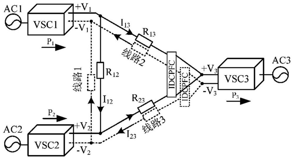
[0051] This embodiment provides a collaborative DC power flow controller circuit topology, the circuit topology is as follows Figure 4 shown.

[0052] In order to cope with various possible power flow dispatching situations, the adjustment goal of the power flow controller should be to flexibly adjust the power flow of the DC power grid to achieve safe power transmission and reduce power loss. In order to realize fast, flexible and high-dimensional DC power flow control, it is necessary to use different DC power flow controllers in combination.

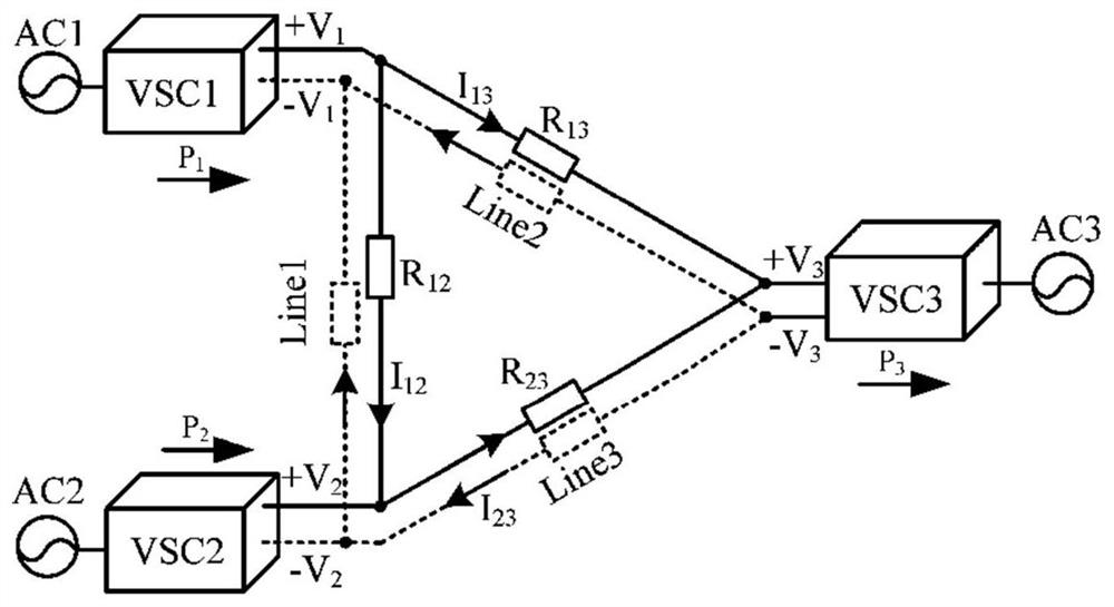
[0053] Below to figure 1 The typical three-terminal ring-network DC transmission system shown is a technical scenario. The principle of the technical solution provided by this embodiment is explained, and the degree of effective improvement in the dimension of power flow control is clarified through sensitivity analysis.

[0054] The circuit topology provided by this embodiment mainly consists of six bidirectional switches (Q 1 , ...


PUM


Abstract

The invention provides a circuit topology structure of a coordinated DC power flow controller, which includes a first VR circuit, a second VR circuit and an IDCPFC circuit, wherein the first VR circuit and the second VR circuit are respectively connected in series with the IDCPFC circuit. At the same time, an operation control method of a cooperative DC power flow controller is provided. The IDCPFC circuit actively controls the power flow of one of the lines 2 or 3, and the first VR circuit or the second VR circuit actively controls the other of the lines 2 or 3. Line flow; when power is transferred from Line 2 to Line 3, the resistance R z works; when power is transferred from line 3 to line 2, the resistor R y Work. The present invention can actively control the power flow of one line, and can also control the power flow of two lines, has the advantages of more comprehensive functions, more applicable occasions, and higher dimension for the power flow controller of the direct current transmission system.

Description

technical field [0001] The invention relates to the field of power electronic converters and flexible direct current transmission, in particular to a circuit topology and operation control method of a coordinated direct current power flow controller (DC Power Flow Controller, DCPFC) facing a multi-terminal direct current power system. Background technique [0002] With the rapid construction of large-scale photovoltaic power stations / wind farms, the DC collection and transmission technologies of cost-effective large-scale new energy stations have attracted increasing attention. HVDC transmission has the advantages of long transmission distance and flexible operation scheduling. It is suitable for the grid connection of new energy stations with longer transmission distances, and has become a research and development hotspot in the field of smart grids. The multi-terminal DC transmission system can realize multi-source power supply and multi-drop power receiving. Compared with...

Claims


Application Information

Patent Timeline
Patent Type & Authority Patents(China)
IPC IPC(8): H02J3/36
CPCY02E60/60
Inventor 朱淼徐莉婷钟旭蔡旭
Owner SHANGHAI JIAOTONG UNIV
Why Eureka
Try Eureka