
A Flexible Pneumatic Gripper with Force Feedback and Stroke

A technology of force feedback and pneumatic clamp, which is applied in the field of robotics, can solve problems such as object falling off, hidden safety hazards, and difficult control, and achieve the effect of enhancing self-adaptability, ensuring synchronization, and increasing the dimension of control

Active Publication Date: 2019-11-12
SUZHOU XINYOUHUA INVESTMENT ADVISOR CO LTD
View PDF10 Cites 0 Cited by
  • Summary
  • Abstract
  • Description
  • Claims
  • Application Information

AI Technical Summary

Problems solved by technology

According to literature search, the publication date is October 26, 2016, and the publication number is CN104959992B, a pneumatic software gripping device, which proposes to change the gripping line of the hand in a pneumatic way to grasp objects, and its structure is simple and cost-effective. Inexpensive, but its gripper is not self-locking, that is, when the air source is suddenly interrupted, the gripper will immediately lose its deformation state and the object will fall off, causing a safety hazard
[0006] Secondly, the gripper itself in this device does not have a stroke function, that is, the finger itself cannot move, and the characteristics of the software gripper adaptive to the object cannot be maximized.
In addition, the lack of feedback mechanism (finger clamping force, finger deformation, object load, etc.) in this device makes it difficult to control

Method used


Image

  • A Flexible Pneumatic Gripper with Force Feedback and Stroke
  • A Flexible Pneumatic Gripper with Force Feedback and Stroke
  • A Flexible Pneumatic Gripper with Force Feedback and Stroke

Examples


Embodiment Construction

[0028] The specific implementation manners of the present invention will be further described in detail below in conjunction with the accompanying drawings and embodiments. The following examples are used to illustrate the present invention, but are not intended to limit the scope of the present invention.

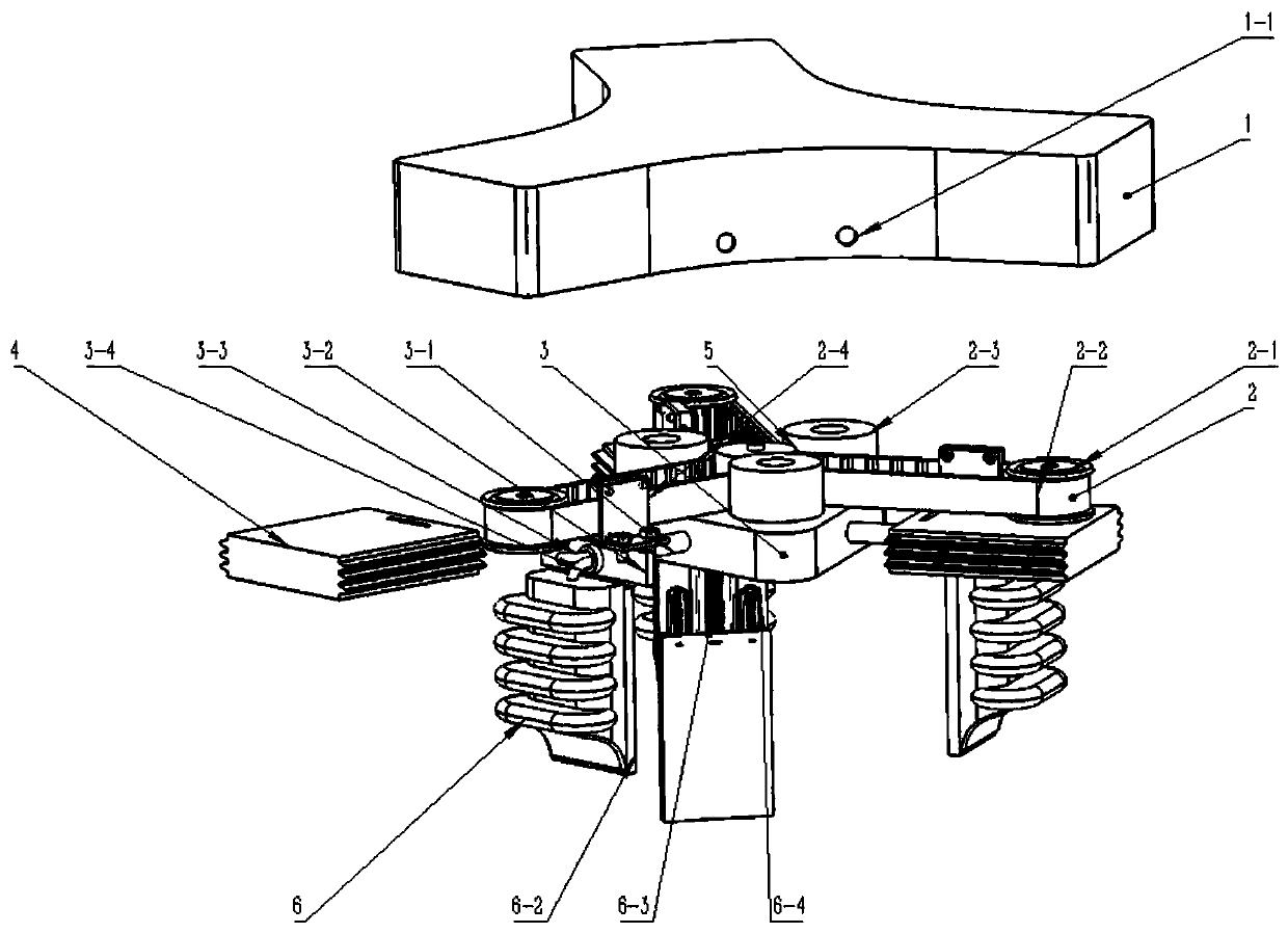
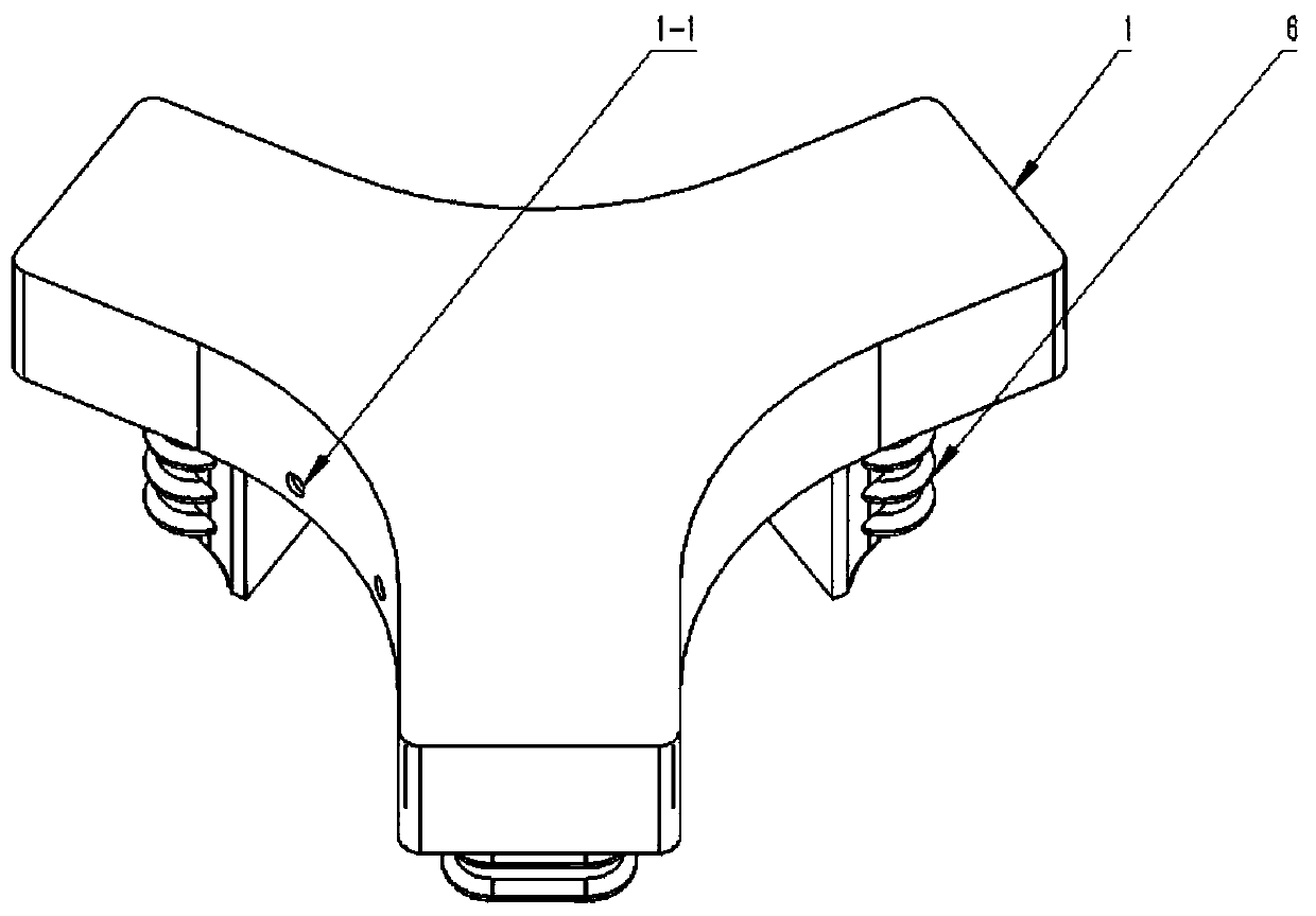
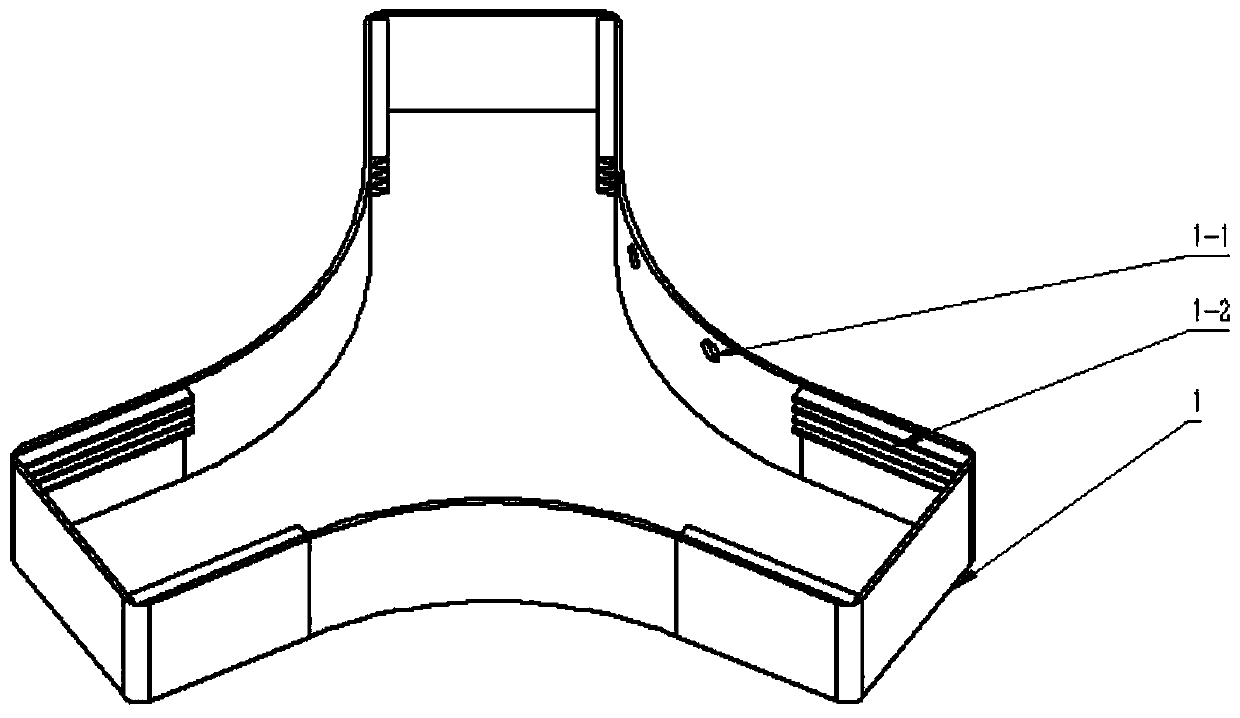
[0029] see Figure 1-Figure 9 , a preferred embodiment of the present invention, the described flexible pneumatic gripper with force feedback and stroke includes a top shell 1, a timing belt unit 2, an intermediate air cavity 3, three sliders 4, and a tension sensor 5 and finger 6. Among them, there are two ports 1-1 connected with the air source on the top shell 1. The purpose of separating air inflation and air extraction here is to realize the self-locking function by using a one-way valve. Evenly distributed in the circumferential direction to form an equilateral triangle, the top shell 1 is provided with a chute 1-2, the slider 4 can slide towards or away from the c...


PUM


Abstract

The invention relates to a flexible pneumatic gripper with force feedback and stroke. The flexible pneumatic gripper comprises a top shell, sliding blocks, a synchronous belt unit, a middle air cavity, a tension sensor, fingers and air conveying pipes, wherein connectors which communicate with an air source are formed in the top shell; a sliding groove is formed in the top shell; the sliding blocks are of hollow structures inside; a notch is formed in one surface of each sliding block; the sliding blocks are arranged on the sliding groove in a sliding manner; one end of the tension sensor is fixed to the top shell; the other end of the tension sensor is fixed to the top of the middle air cavity; air ends of the fingers are connected with the notches of the sliding blocks; one-way air valves are arranged in the air conveying pipes; one ends of the air conveying pipes are connected with the middle air cavity; the other end of each air conveying pipe is divided into two air pipes; the first air pipes enter the sliding blocks and communicate with the air ends of the fingers; and the second air pipes are arranged in the hollow structures in the sliding blocks and communicate with the hollow structures of the sliding blocks. The flexible pneumatic gripper is good in reliability, high in safety, high in control dimension and high in adaptability, and can better adapt to modern factories.

Description

technical field [0001] The invention belongs to the field of robots, and in particular relates to a flexible pneumatic gripper with force feedback and stroke. Background technique [0002] With the continuous development of science and technology, the traditional manual work mode is gradually replaced by automation equipment. Nowadays, industrial robots with various functions are becoming more and more common in all walks of life. Common factory operations such as spraying, assembly, welding, handling, loading and unloading, etc. can basically be performed by industrial robots. The popularity of robots has greatly improved the production efficiency of factories and saved labor costs. [0003] Industrial robots usually consist of a robotic arm and a gripper. Industrial manipulators are connected in series, SCARA is the most common, and most of them are 4-axis and 6-axis. The gripper, also known as the end effector, is one of the necessary execution components for industri...

Claims


Application Information

Patent Timeline
Patent Type & Authority Patents(China)
IPC IPC(8): B25J15/12
CPCB25J15/12
Inventor 戴军王宏军
Owner SUZHOU XINYOUHUA INVESTMENT ADVISOR CO LTD
Learn More