
Echo cancellation method and device based on time delay estimation

A technology of delay estimation and echo cancellation, applied in the field of signal processing, can solve the problems of synchronous resampling of loudspeaker signal and microphone signal, unable to achieve synchronous resampling of reference signal and microphone signal, large error of delay estimation, etc.

Active Publication Date: 2018-01-19
IFLYTEK CO LTD
View PDF5 Cites 21 Cited by
  • Summary
  • Abstract
  • Description
  • Claims
  • Application Information

AI Technical Summary

Problems solved by technology

For example, a distributed intelligent hardware device with only single-ended operation authority cannot achieve synchronous resampling of the reference signal and the microphone signal. For example, in daily households, the TV box is used to control the TV. Since the TV box and the TV are mostly provided by different manufacturers, Assume that as a TV box manufacturer, in the voice control of the TV box, it is necessary to perform echo cancellation on the sound played by the TV, and at this time only has the operation authority of the TV box, that is, it can only obtain the source signal transmitted from the TV box to the TV and the microphone of the TV box Collecting signals, among them, the source signal sent by the TV box to the TV is used as a reference signal, and the signal collected by the microphone of the TV box is used as a microphone signal. It is impossible to re-sample the speaker signal and the microphone signal synchronously. At this time, it is necessary to estimate the reference signal and the microphone signal. The delay of the signal, and then realize the echo cancellation according to the delay
[0004] It can be seen that the accuracy of time delay estimation directly affects the effect of echo cancellation. Due to the complex and changeable environment in actual application scenarios, the existing echo cancellation technology based on time delay estimation has a large error in time delay estimation, and the effect of echo cancellation is relatively large. still needs to be improved

Method used


Image

  • Echo cancellation method and device based on time delay estimation
  • Echo cancellation method and device based on time delay estimation
  • Echo cancellation method and device based on time delay estimation

Examples


example 1

[0109] Example 1: Select the position corresponding to the frame with the largest cross-correlation in the cross-correlation between the calculated reference signal and the microphone signal of each frame as the current delay position, and determine the current delay according to the current delay position and the position of the reference signal estimated value.

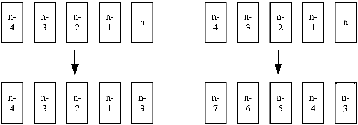
[0110] For example, taking the current reference signal frame as the benchmark, assuming that the reference signal is the 50th frame, there are 30 frames of microphone signals within the time delay analysis range, which are the 20th to 50th frames of microphone signals, respectively. The reference signals are compared, and if the cross-correlation between the current reference signal of the 50th frame and the microphone signal of the 25th frame is the largest, the current estimated delay value is 50−25=25. Of course, if the number of frames of the reference signal (eg, 18) is less than 30, the microphone signals to ...


PUM


Abstract

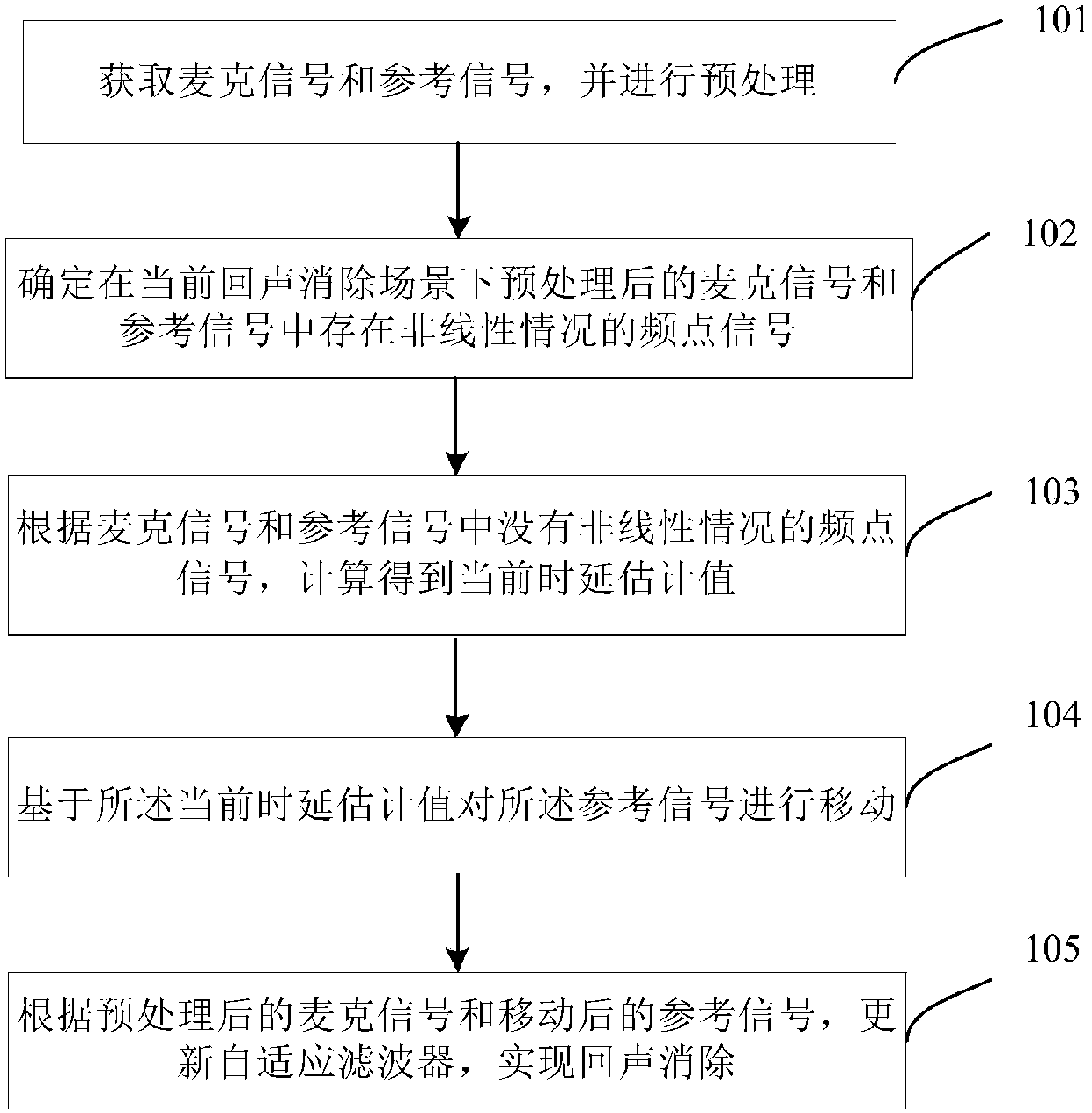
The invention discloses an echo cancellation method and device based on time delay estimation. The method comprises the steps that microphone signals and reference signals are acquired and preprocessed; frequency-point signals with nonlinear conditions in the preprocessed microphone signals and reference signals in a current scene are determined; according to frequency-point signals without nonlinear conditions in the microphone signals and the reference signals, a current time delay estimation value is obtained through calculation; based on the current time delay estimation value, the reference signals are moved; according to the preprocessed microphone signals and the moved reference signals, a self-adaptive filter is updated, and echo cancellation is achieved. By means of the method anddevice, the accuracy of time delay estimation can be improved, and the echo cancellation effect is improved.

Description

technical field [0001] The invention relates to the field of signal processing, in particular to an echo cancellation method and device based on time delay estimation. Background technique [0002] With the continuous development of information technology, all kinds of distributed intelligent hardware are widely used in various fields. As an indispensable link in the interaction of smart devices, echo cancellation has always been a research hotspot for technicians in related fields. [0003] Echo cancellation is a processing method that prevents the far-end sound from returning by eliminating or removing the far-end audio signal picked up by the local microphone. The existing typical echo cancellation scheme is based on the time delay estimation method, and the calculation reference The linear correlation relationship between the signal and the microphone signal, and the time delay corresponding to the maximum cross-correlation is selected as the device time delay, and the ...

Claims


Application Information

Patent Timeline
Patent Type & Authority Applications(China)
IPC IPC(8): G10L21/0208G10L21/0216
CPCH04M9/082G10L21/0216G10L21/0208G10L21/0232G10L2021/02082G10L2021/02163H04R3/04H04R29/004
Inventor 李明子马峰王海坤王智国胡国平
Owner IFLYTEK CO LTD
Learn More