Car body front longitudinal beam test method

A test method and technology for front longitudinal beams, which are applied in special data processing applications, instruments, electrical digital data processing, etc., can solve the problems that cannot be applied to the design and manufacture of pure aluminum body, the strength and weldability are different, and the aluminum body cannot be applied. and other problems, to achieve the effect of shortening the research and development time, ensuring the accuracy, and saving a lot of investment

Inactive Publication Date: 2018-01-19
CH AUTO TECH CORP CO LTD
View PDF3 Cites 6 Cited by
  • Summary
  • Abstract
  • Description
  • Claims
  • Application Information

AI Technical Summary

Problems solved by technology

For the aluminum body, due to the different physical properties of aluminum and steel materials, the strength and weldability of the two are different, so that the traditional welding technology of stamping parts cannot be applied to the aluminum body. , the anti-collision design also needs to start from scratch
[0005] Among them, the front longitudinal beam used for energy absorption at the front of the pure aluminum body plays an important role in ensuring the driving safety of the vehicle. However, due to the hardening and failure of the aluminum profile under high-speed strain, the traditional stamping parts welding technology The technology of steel body front side beams is no longer applicable to the design and manufacture of pure aluminum body
At the same time, the front side beam of the vehicle body needs to be tested on the crash performance of the vehicle body together with the whole vehicle to obtain the design results of the crash safety requirements of the vehicle body, and then it can be adopted to realize the mass production of the vehicle. In other words, a large number of designs, manufactures, and tests will greatly increase investment in automotive R&D and extend the R&D cycle
Furthermore, in the pure aluminum body, the design and testing of the front longitudinal beam of the body poses new challenges to the R&D technicians in this field.

Method used


Image

  • Car body front longitudinal beam test method
  • Car body front longitudinal beam test method
  • Car body front longitudinal beam test method

Examples


Embodiment Construction

[0031] In order to have a clearer understanding of the technical features, purposes and effects of the invention, the specific implementation manners of the present invention will now be described with reference to the accompanying drawings, in which the same reference numerals represent the same parts.

[0032] In this article, "schematic" means "serving as an example, example or illustration", and any illustration or implementation described as "schematic" should not be interpreted as a more preferred or more advantageous Technical solutions.

[0033] In order to make the drawings concise, the figures in each figure only schematically show the relevant parts of the present invention, and do not represent the actual structure of the product. In addition, to make the drawings concise and easy to understand, in some drawings, only one of the components having the same structure or function is schematically shown, or only one of them is marked.

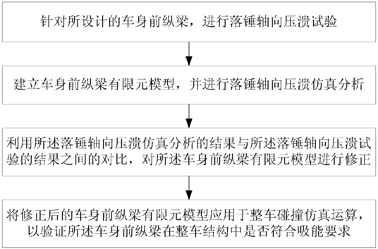
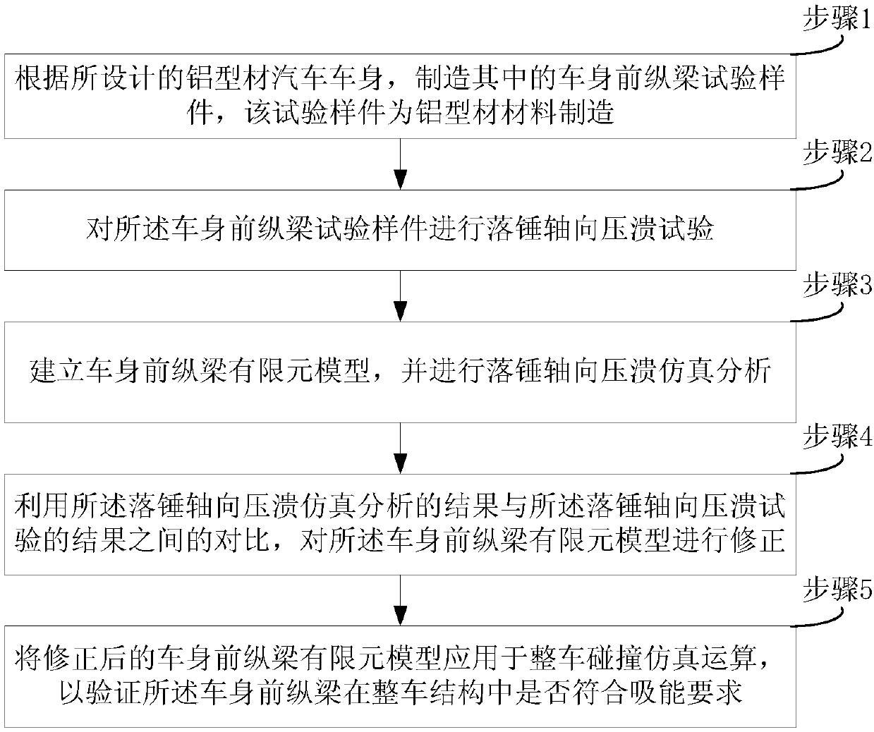
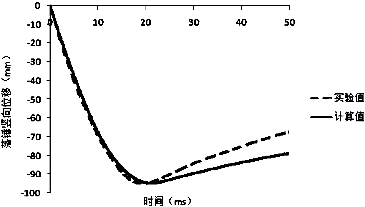
[0034] Such as figure 1 Shown,...


PUM


Abstract

The invention provides a car body front longitudinal beam test method. According to the method, first, a drop hammer axial crushing test is performed on a designed car body front longitudinal beam toobtain actual test data, then the actual test data is utilized to establish a relevant finite element model, the finite element model is utilized to perform simulation analysis on the car body front longitudinal beam and is corrected, and the finite element model of the car body front longitudinal beam after correction is applied to whole-car crash simulation operation to verify whether the car body front longitudinal beam meets an energy absorption requirement in a whole car structure. Through the method, simulation operation is adopted to replace a large quantity of actual tests, and by useof the advantages of being repetitive, convenient to improve, high in result acquisition speed and the like of simulation operation, a large amount of investment consumed in an actual test is saved, and research and development time is shortened. Meanwhile, the finite element model of the car body front longitudinal beam is corrected through comparison of the simulation analysis result and the actual drop hammer axial crushing test result, so that the accuracy of a simulation calculation result is guaranteed.

Description

technical field [0001] The invention relates to the field of automobile design testing, in particular to a testing method for a front longitudinal beam of a vehicle body. Background technique [0002] The steel body of the existing car adopts traditional stamping parts welding technology. In terms of car safety, the design of the axial crush deformation of the front longitudinal beam of the car body is used to effectively absorb the kinetic energy during the impact and avoid excessive impact on the members of the car. The existing stamping parts welding technology is mature and widely used. [0003] For the purpose of saving energy and reducing consumption, in recent years, the automobile industry is undergoing new changes and new innovations. One of the development directions is to reduce the quality of the vehicle to reduce consumption. In particular, with the popularization of electric vehicles, reducing the quality of the vehicle has become one of the technical breakth...

Claims


Application Information

Patent Timeline
IPC IPC(8): G06F17/50
Inventor 陆群武晓林
Owner CH AUTO TECH CORP CO LTD
Why Eureka
Try Eureka