Planomiller control system

A control system and gantry milling machine technology, applied in the field of machinery, can solve the problems of high maintenance frequency, poor reliability of machine tools, and inability to give full play to large machine tools, and achieve the effects of easy operation, simplified structure, and improved anti-interference ability.

Inactive Publication Date: 2018-01-19
牛誉博
View PDF0 Cites 0 Cited by
  • Summary
  • Abstract
  • Description
  • Claims
  • Application Information

AI Technical Summary

Problems solved by technology

[0003] Because the entire control system of the original X2010A gantry milling machine uses a large number of contact elements such as relays, contactors, and travel switches, the feed drive uses a silicon controlled-DC motor system (SCR-D), and the trigger circuit uses separate components, resulting in the entire The reliability of the machine tool in operation is poor, the maintenance frequency is high, and the role of large machine tools cannot be fully utilized

Method used


Image

  • Planomiller control system
  • Planomiller control system

Examples


Embodiment Construction

[0012] The present invention will be further described below in conjunction with drawings and embodiments.

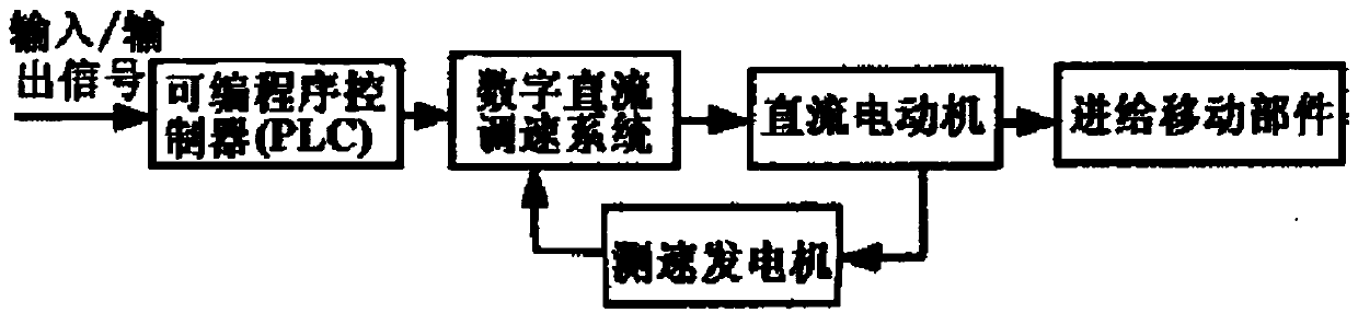
[0013] Such as figure 1 , under the premise of keeping the mechanical transmission system and operation mode of the original X2010A gantry milling machine unchanged, in view of the characteristics of the machine tool and the problems existing in the control system, the control system uses a programmable logic controller (PLC) as the main controller to coordinate The action between the moving parts replaces the relay-contactor control circuit, and replaces the thyristor rectifier system with a digital DC speed control device.

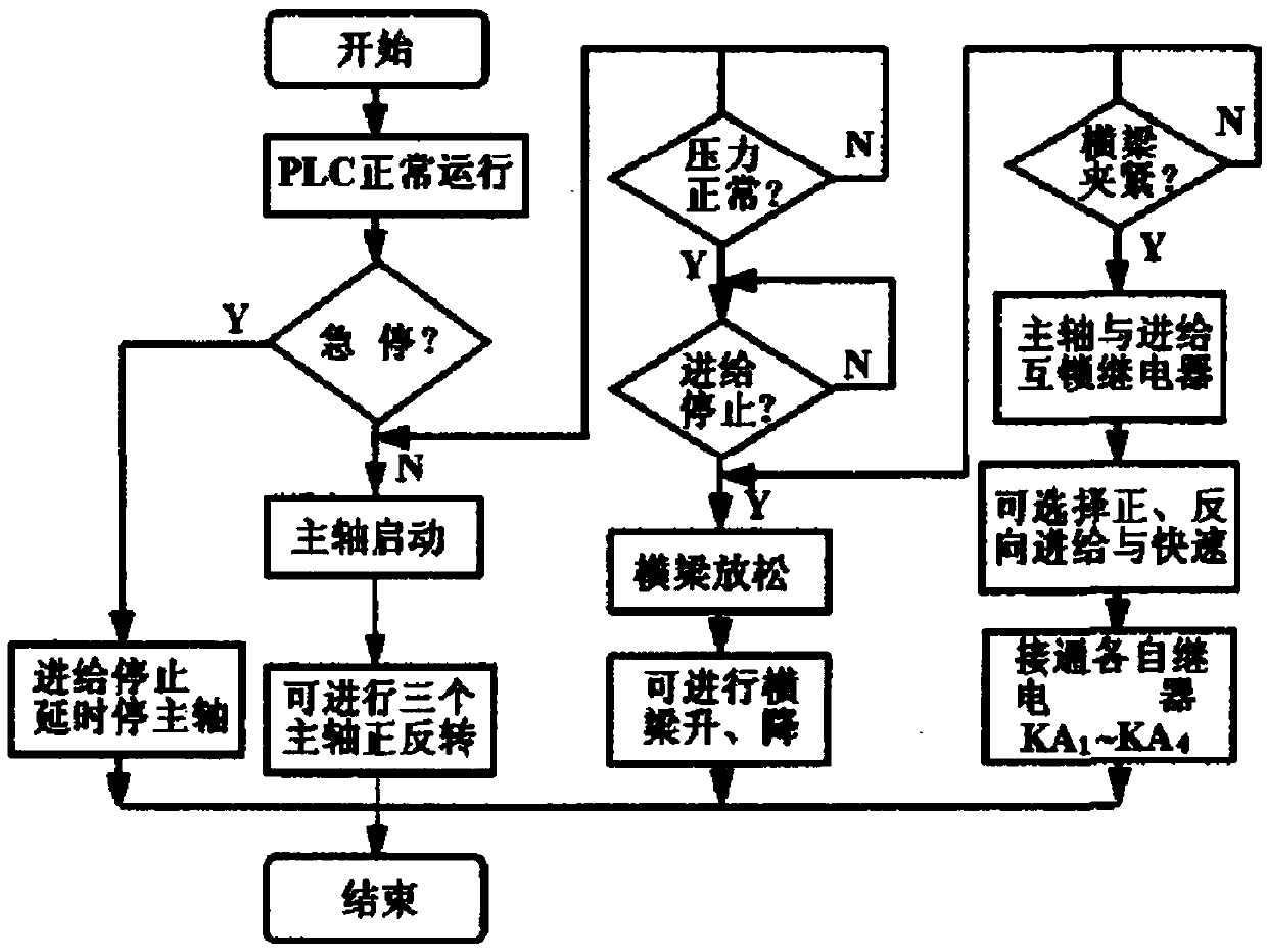
[0014] Such as figure 2 , The main movement of the gantry milling machine includes the rotational movement of the three spindles, the feed movement of the table and the three spindles, and the lifting movement of the beam. Since the control relationship between the start and stop of the hydraulic pump, the selection switch of the worktable and ...


PUM


Abstract

A planomiller control system is provided. A PLC (programmable logic controller) is used as a master controller to coordinate the operation of various moving parts and to replace a relay-contactor to control a circuit. A digital DC speed control device replaces a SCR rectifier system. Feed movement is achieved by a digital DC speed control system and stable start and stop of the feed movement is achieved by parameter adjustment. An operation panel is provided with an armature voltage indicator, an armature current indicator, an excitation current indicator, and a motor speed indicator so as toachieve direct and clear display and facilitate operation. A machine tool control system is greatly simplified in structure, reduces many sources of interference and improves the system anti-interference ability.

Description

Technical field [0001] The invention relates to a control system for a gantry milling machine, which is suitable for the mechanical field. Background technique [0002] The gantry milling machine is a heavy-duty machining equipment for processing large parts. It is often used to mill the surface of parts, and it can also perform other forms of processing such as block cutting and drilling. The movement of the original X2010A type gantry milling machine is the tool rotation of the left and right horizontal spindle boxes and one vertical spindle box. The spindles are driven by AC asynchronous motors respectively, and mechanical step-change is adopted. The feed movement includes the front and rear movement of the worktable, the left and right horizontal headstock moves up and down along the column, and the vertical headstock moves left and right along the beam (shared with one motor, using selector switch and electromagnetic clutch for centralized transmission). The driving mot...

Claims


Application Information

Patent Timeline
Patent Type & Authority Applications(China)
IPC IPC(8): G05B19/414B23Q5/22
Inventor 牛誉博
Owner 牛誉博
Why Eureka
Try Eureka