
A Magnetic Suspension Control Sensitive Gyroscope with Co-located Detection and Control

A sensitive gyro and magnetic levitation technology, applied in the direction of rotating gyroscope, etc., can solve problems such as reducing the translational suspension accuracy and deflection angle accuracy of the gyro rotor, reducing the instantaneous gyro control torque output, and reducing the gyro control torque output time, etc. The effect of high translational suspension accuracy, high control torque accuracy, and high gyro control torque accuracy

Active Publication Date: 2020-05-22
BEIJING INSTITUTE OF PETROCHEMICAL TECHNOLOGY
View PDF14 Cites 0 Cited by
  • Summary
  • Abstract
  • Description
  • Claims
  • Application Information

AI Technical Summary

Problems solved by technology

Due to the measurement error of the conversion matrix, and the error changes with time, temperature, and stress, the translational suspension accuracy and deflection angle accuracy of the gyro rotor are reduced, which in turn affects the gyro control torque accuracy of the sensitive gyro
In addition, the protection bearings of the above schemes all use cylindrical deep groove ball bearings. When the gyro rotor precesses to output the gyro control torque, the protection bearing will limit the deflection angle of the gyro rotor, thereby reducing the output time of the gyro control torque, thereby reducing the instantaneous The size of the gyro control torque output

Method used


Image

  • A Magnetic Suspension Control Sensitive Gyroscope with Co-located Detection and Control
  • A Magnetic Suspension Control Sensitive Gyroscope with Co-located Detection and Control
  • A Magnetic Suspension Control Sensitive Gyroscope with Co-located Detection and Control

Examples


Embodiment Construction

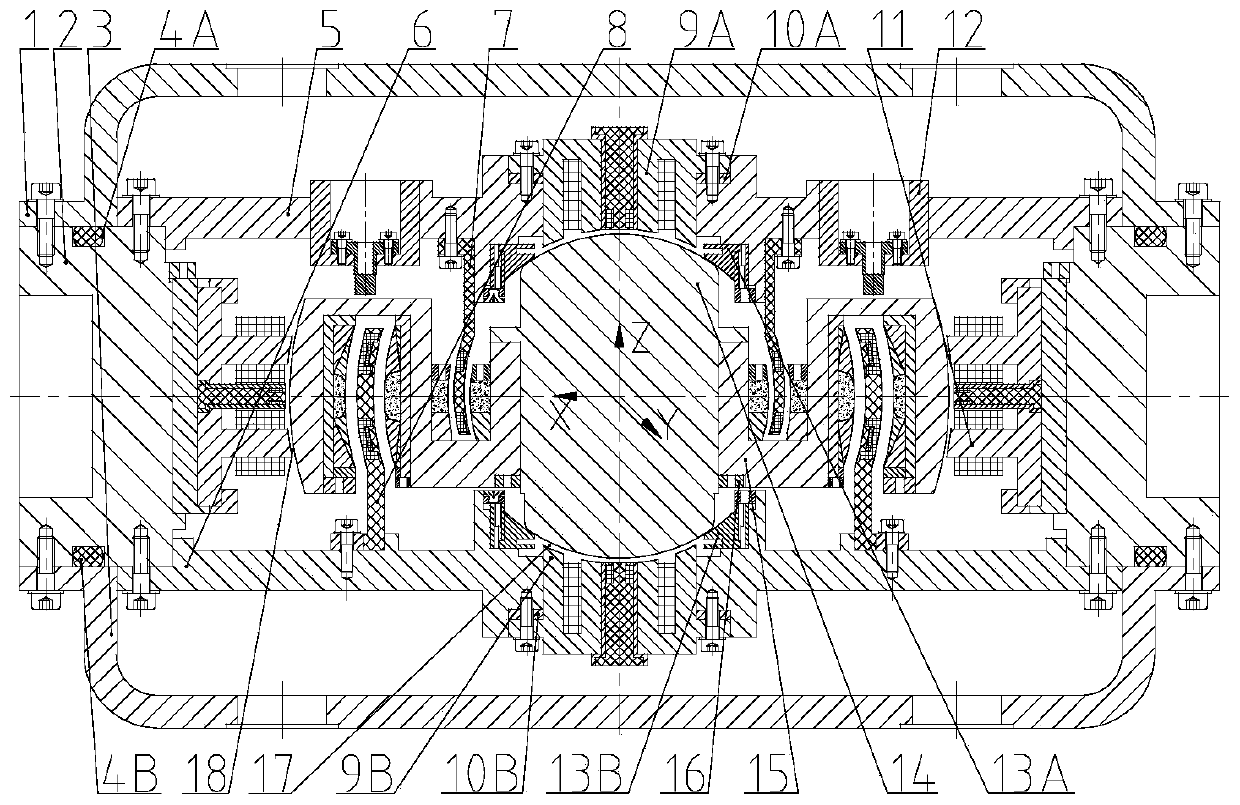
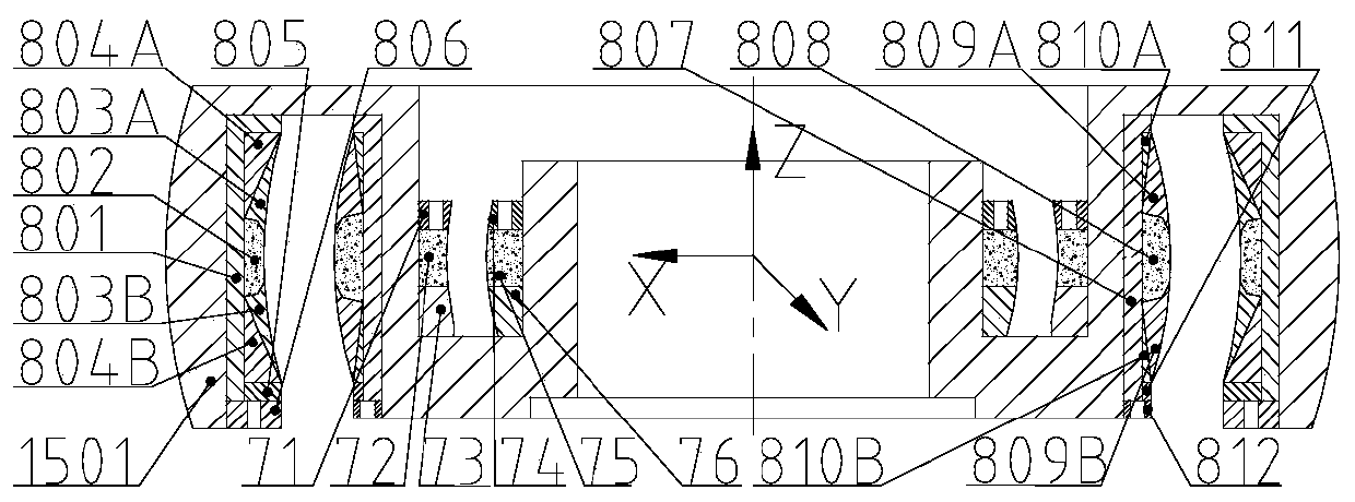
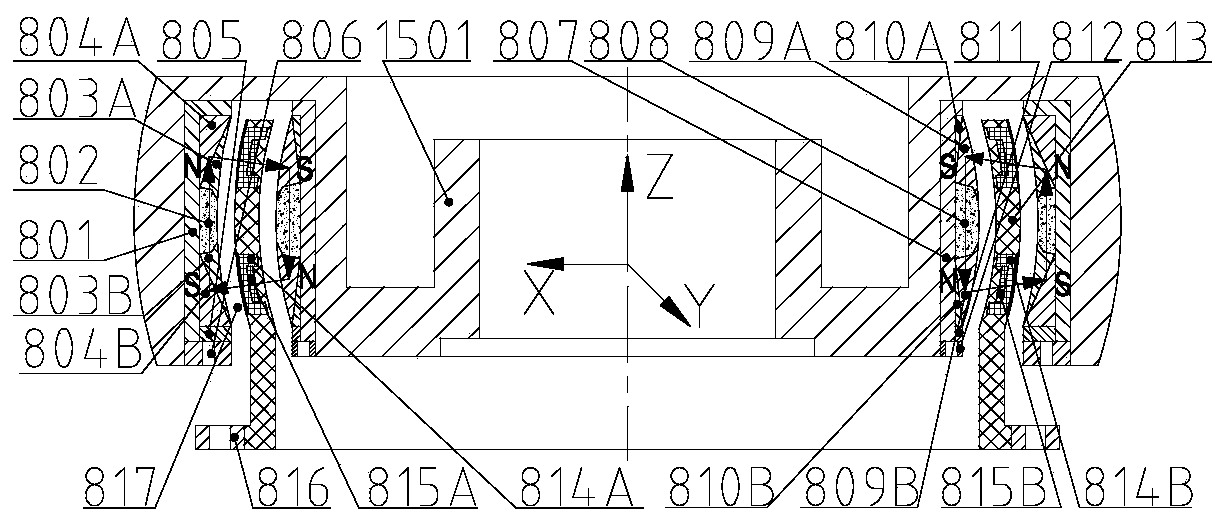
[0018] Such as figure 1 As shown, a magnetic levitation control sensitive gyroscope with detection and control co-location includes a static part and a rotating part. It is characterized in that the static part includes: an upper sealing cover 1, a middle gyroscope room 2, a lower sealing cover 3, an upper sealing ring 4A, a lower Sealing ring 4B, upper gyro housing 5, lower gyro housing 6, motor assembly 7 stator, Lorentz force magnetic bearing 8 stator, upper axial spherical magnetic bearing 9A stator, lower axial spherical magnetic bearing 9B stator, upper adjusting gasket ring 10A, lower adjusting pad ring 10B, radial spherical magnetic bearing 11 stator, deflection displacement sensor assembly 12, upper protective bearing 13A, lower protective bearing 13B; the rotating part includes: gyro inner shaft 14, gyro outer turntable assembly 15 and gyro rotor lock Female 16; the upper sealing cover 1 is located at the axial upper end of the middle gyroscope room 2, and is fixed o...


PUM


Abstract

The invention relates to a detection-control co-located magnetically suspended control sensitive gyroscope which comprises a stationary part and a rotating part. The stationary part comprises an uppersealing cap, a middle gyro chamber, a lower sealing cap, a sealing ring, an upper gyro chamber, a lower gyro chamber, a motor assembly stator, a Lorentz force magnetic bearing stator, an axial spherical magnetic bearing stator, an adjustment washer ring, a radial spherical magnetic bearing stator, a deflection displacement sensor assembly and a protection bearing; the rotating part includes a gyro inner rotating shaft, a gyro outer rotating disc assembly and a gyro rotor lock net. The displacement detection point and magnetic bearing control point co-located magnetically suspended control sensitive gyroscope eliminates errors caused by a sensor and a magnetic bearing transfer matrix, and improves gyroscopic control torque precision and attitude sensitive precision. In addition, protectiveclearances and magnetic clearances between the stators and the rotors are spherical shells, negative moments of a translational motion magnetic bearing caused by rotor deflection can be eliminated, rotor deflection angle is increased, and gyroscopic control torque and acting time can be increased.

Description

technical field [0001] The invention relates to a sensitive gyroscope for magnetic levitation control, in particular to an inner rotor magnetic levitation spherical control sensitive gyroscope in which the detection point of the rotor displacement coincides with the translational control point of the magnetic bearing and can be used for attitude control and control of very stable and ultra-quiet space-based platforms. attitude detection. Background technique [0002] The inertial mechanism based on momentum exchange has the advantages of high control precision and long life, and has been widely used in the attitude control of spacecraft platforms. The inertial mechanism supported by traditional mechanical bearings has zero-crossing friction, viscous moment and mechanical vibration, and the vibration is uncontrollable, and the precision of control torque is low. The magnetic suspension inertial mechanism adopts magnetic suspension bearing support technology, which eliminates...

Claims


Application Information

Patent Timeline
Patent Type & Authority Patents(China)
IPC IPC(8): G01C19/24G01C19/08
Inventor 刘强姚舒晏吴波赵明师胡灯亮
Owner BEIJING INSTITUTE OF PETROCHEMICAL TECHNOLOGY
Learn More