
Vertical coordinated vibration isolation or reduction device and application method thereof

A vertical and insulation reduction technology, applied in the direction of earthquake-proof, protective buildings/shelters, building components, etc., can solve the problems of poor viscous damping, poor sealing, affecting structural performance, and unstable performance, so as to achieve good sealing, Large shear area, excellent vibration isolation effect

Active Publication Date: 2018-01-19
SOUTHEAST UNIV
View PDF9 Cites 9 Cited by
  • Summary
  • Abstract
  • Description
  • Claims
  • Application Information

AI Technical Summary

Problems solved by technology

Viscoelastic materials provide a new idea for increasing the energy dissipation capacity of the spring vibration isolation system, and solve the problem of poor sealing performance of viscous damping and unstable performance. Load (such as building self-weight, etc.), viscoelastic materials under static load for a long time will easily lead to tearing and falling off, affecting structural performance
Most of the devices fail to consider the adverse effects of the static displacement generated by the static load of the building on the deformation of the viscoelastic material under the actual working condition, or the design is too complicated even though the actual situation is considered

Method used


Image

  • Vertical coordinated vibration isolation or reduction device and application method thereof
  • Vertical coordinated vibration isolation or reduction device and application method thereof
  • Vertical coordinated vibration isolation or reduction device and application method thereof

Examples


Embodiment Construction

[0021] The technical solutions of the present invention will be described in detail below, but the protection scope of the present invention is not limited to the embodiments.

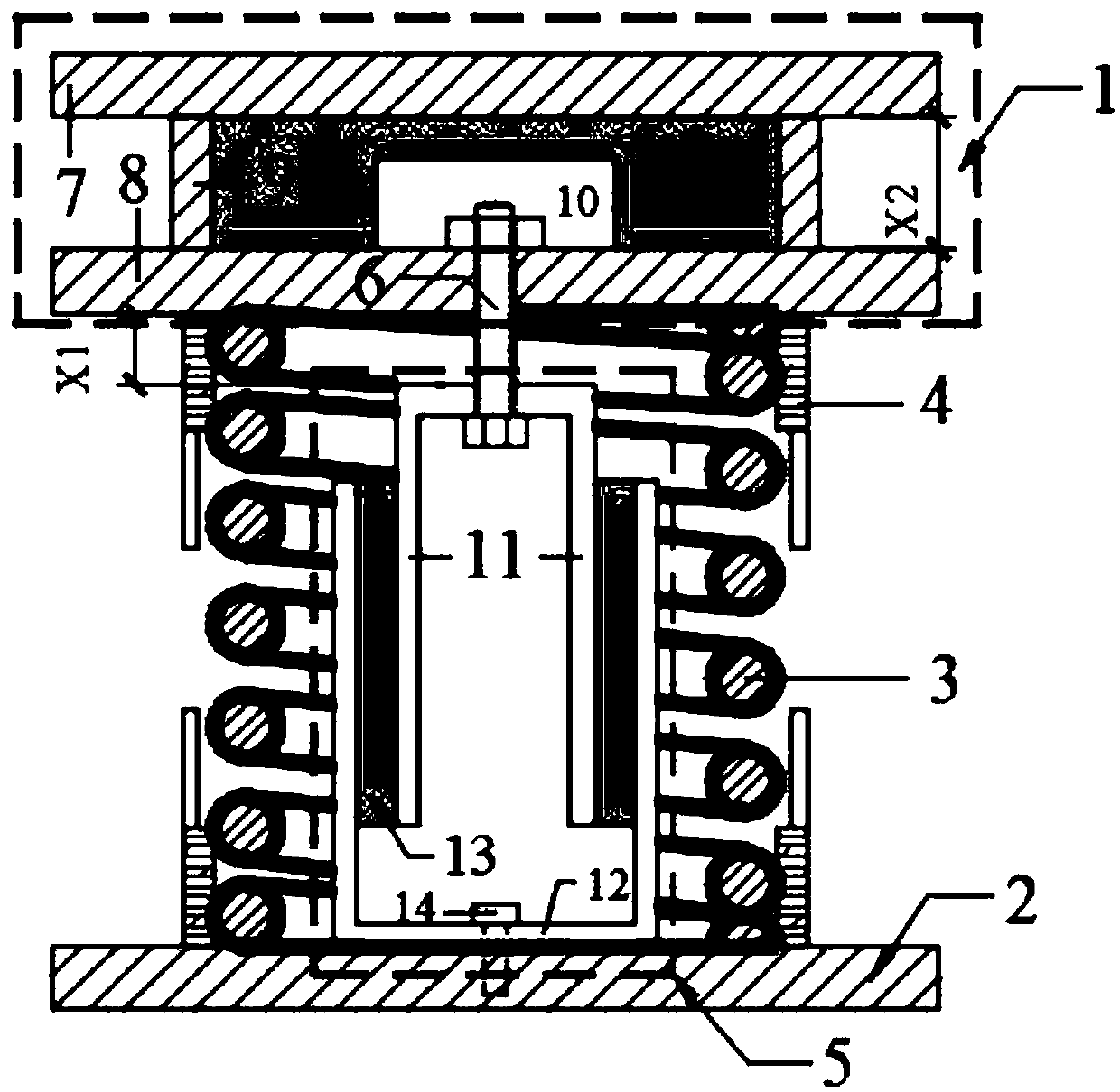
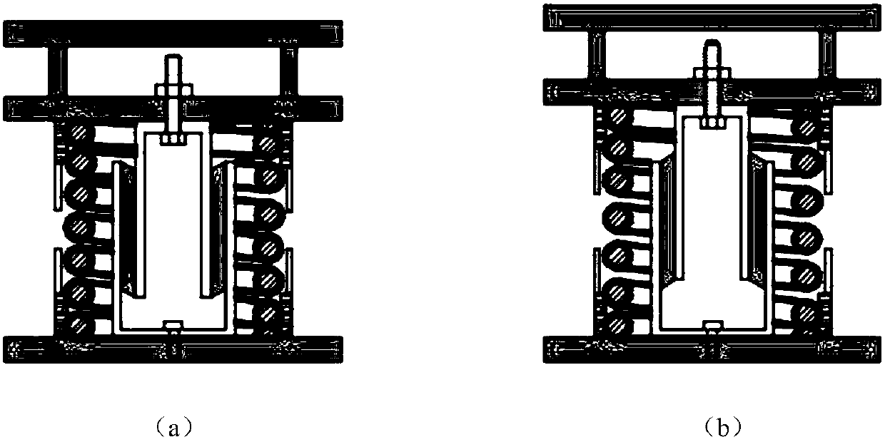
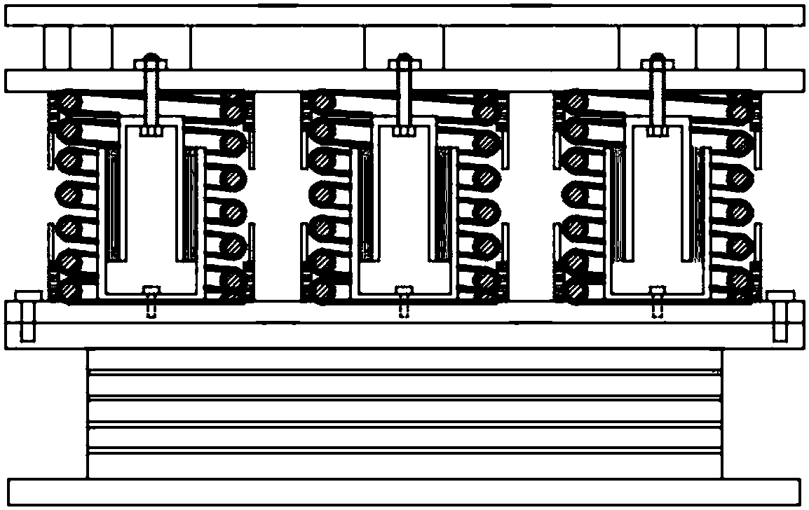
[0022] Example: such as figure 1 , 2 As shown, a vertical cooperative vibration isolation / vibration reduction device includes an upper support 1 and a lower steel plate 2 corresponding to the upper and lower sides and arranged horizontally, and several sets of coil springs evenly distributed between the upper and lower steel plates 1 and 2 3 and combined viscoelastic cylinder damper 5.

[0023] The upper bracket is composed of a bracket top plate 7, a bracket bottom plate 8 and a side wing plate 9. The bracket top plate 7 and the bracket bottom plate 8 are parallel to each other up and down. The side wing plate 9 is an annular plate. The upper end surface and the lower end surface are fixed as one.

[0024] The bottom surface of the upper bracket 1 and the top surface of the lower steel plate 2 are ...


PUM


Abstract

The invention provides a vertical coordinated vibration isolation or reduction device and an application method thereof. The device comprises an upper support and a lower steel plate which are horizontally arranged, a spiral spring which is vertically clamped between the upper support and the lower steel plate and a combined viscous-elastic cylinder damper which is coaxially installed in the spiral spring; the upper support comprises a circumferential side wing plate and a support top board and a support base board which are respectively fixed at an upper end and a lower end of the side wing plate; the combined viscous-elastic cylinder damper comprises an inner sleeve and an outer sleeve which are coaxially arranged and a viscous-elastic damping layer which is between the inner sleeve andthe outer sleeve by high temperature vulcanization; the combined viscous-elastic cylinder damper passes through and is fixed on the support base plate through a bolt at the top of the inner sleeve; abottom of the outer sleeve is fixed on the lower steel plate. Based on the spring vibration isolation system, the invention adopts a viscous-elastic damping material to increase the energy consumptionability of the device system with large damping ratio, stable performance, good sealing property and suitable for engineering application, and designs a complete spring damping cooperative working system suitable for vertical load-bearing structure to withstand vertical excitation, which plays an excellent role in vibration isolation and vibration reduction.

Description

technical field [0001] The invention relates to a structure vibration control device, in particular to a vertical vibration isolation / shock reduction device. Background technique [0002] Structural vibration control is a new type of anti-vibration / seismic measure, which consumes or isolates vibration / vibration energy by setting vibration reduction / vibration / vibration / vibration / seismic devices in the structure, or applies external energy to counteract the impact of external excitation on the structure. The role of structure. In the field of building vibration control, vertical vibration isolation has always been a difficult problem to solve. In design codes, for long-span structures, important building facilities, and structures with irregular shapes, vertical seismic action must be considered. At the same time, the traffic load generated by urban rail transit is mainly based on continuous vertical dynamic excitation, which has a non-negligible vibration impact on adjacent...

Claims


Application Information

Patent Timeline
IPC IPC(8): E04B1/98E04H9/02
Inventor 徐赵东盖盼盼戴军
Owner SOUTHEAST UNIV
Learn More