Ball screw type self-energized semi-active suspension actuator and control method thereof
What is Al technical title?
Al technical title is built by PatSnap Al team. It summarizes the technical point description of the patent document.
A semi-active suspension, ball screw type technology, applied in suspension, elastic suspension, transportation and packaging, etc., can solve the problems of low energy feeding efficiency of the system, inability to adjust parameters for different models, shortening the service life of generators, etc.
Active Publication Date: 2018-01-19
XIAN UNIV OF SCI & TECH
View PDF6 Cites 7 Cited by
Summary
Abstract
Description
Claims
Application Information
AI Technical Summary
This helps you quickly interpret patents by identifying the three key elements:
Problems solved by technology
Method used
Benefits of technology
Problems solved by technology
However, the ordinary ball screw structure in the prior art will cause the generator to rotate forward and reverse continuously, which will not only cause a large amount of inertia loss, the system energy feeding efficiency will be low, but also the service life of the generator will be shortened, and the system reliability will be poor
For example, the ball screw type shock absorber involved in the "ball screw type inerter with mechanically variable inertial capacity coefficient" disclosed in the Chinese invention patent with the application number of 201410650452.4 mainly uses a mechanical structure to slow down the instantaneous vibration of the road surface. Impact, but once processed and manufactured, its various parameters are determined, and the parameters cannot be adjusted according to different road conditions and different models, and there are certain limitations
Method used
Image
Click on the blue label to locate the original text in one second.
Reading with bidirectional positioning of images and text.
Examples
Embodiment Construction
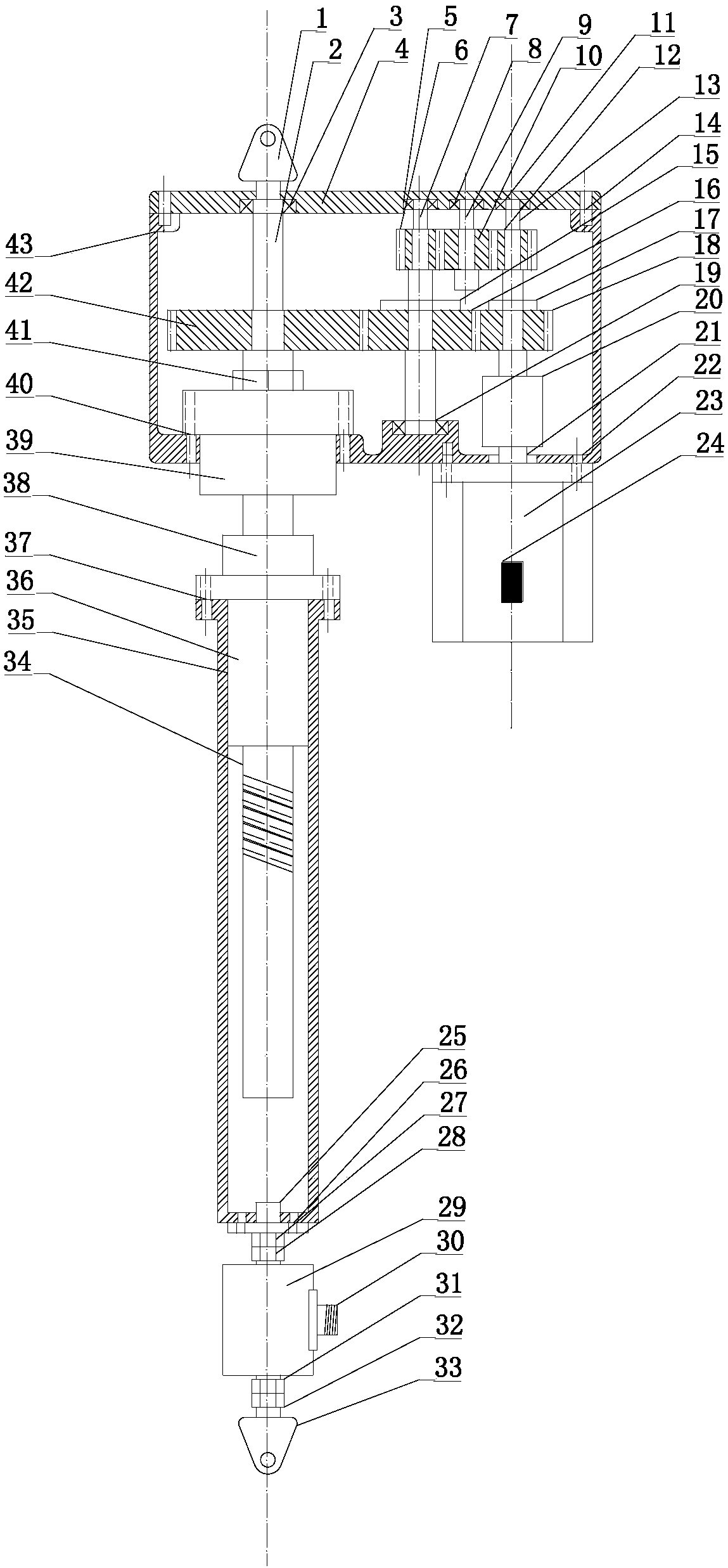
[0111] The ball screw type self-powered semi-active suspension actuator of the present invention includes an actuator body and an actuator control system, such as figure 1 As shown, the actuator body includes an upper housing 43 and a lower housing 35, and the upper housing 43 is provided with a screw shaft 2, a first transmission shaft 7, a second transmission shaft 9 and an output shaft 13, The top of the upper housing 43 is provided with an upper housing cover 4, and the upper housing cover 4 is embedded with a screw shaft bearing 3 for supporting and installing the screw shaft 2, and for supporting and installing the first transmission shaft 7. The first transmission shaft upper end bearing 5, the second transmission shaft bearing 8 for supporting and installing the second transmission shaft 9, and the output shaft bearing 11 for supporting and installing the output shaft 13, the bottom of the upper housing 43 is embedded with The fixed support seat 39 located below the sc...
PUM
Abstract
The invention discloses a ball screw type self-energized semi-active suspension actuator. The ball screw type self-energized semi-active suspension actuator comprises an actuator body and an actuatorcontrol system. The actuator body comprises an upper shell, a lower shell, a lead screw shaft, a first transmission shaft, a second transmission shaft, an output shaft, a direct current brushless motor, a ball screw, a lead screw fixing nut, a lead screw shaft gear, a first transmission shaft first gear, a first transmission shaft ratchet wheel, a first transmission shaft second gear, a second transmission shaft gear, an output shaft first gear, an output shaft second gear, a lead screw nut and a cross-shaped connector. The actuator control system comprises an actuator controller, a computer,a vehicle speed sensor, a road surface unevenness displacement sensor, an unsprung mass displacement sensor, a sprung mass displacement sensor and an actuator speed sensor. The invention further discloses a control method of the ball screw type self-energized semi-active suspension actuator. By adopting the ball screw type self-energized semi-active suspension actuator, a large amount of inertia loss is avoided, the energy feedback efficiency is improved, and the working stability and the reliability are high.
Description
technical field [0001] The invention belongs to the technical field of automobile suspension systems, and in particular relates to a ball screw type self-powered semi-active suspension actuator and a control method thereof. Background technique [0002] During the driving process of the vehicle, the relative displacement between the sprung mass and the unsprung mass of the vehicle will be caused due to the unevenness of the road surface, which will cause the vehicle to vibrate. The suspension system is a key component that determines the dynamic performance of the vehicle, and it determines the ride comfort and ride comfort of the vehicle. Due to the fixed parameters such as stiffness and damping of the traditional passive suspension, the vibration reduction effect of the car is greatly limited, and the suspension vibration reduction performance cannot be changed in time with the change of the road surface excitation. The semi-active suspension can change the stiffness or da...
Claims
Application Information
Patent Timeline
Application Date:The date an application was filed.
Publication Date:The date a patent or application was officially published.
First Publication Date:The earliest publication date of a patent with the same application number.
Issue Date:Publication date of the patent grant document.
PCT Entry Date:The Entry date of PCT National Phase.
Estimated Expiry Date:The statutory expiry date of a patent right according to the Patent Law, and it is the longest term of protection that the patent right can achieve without the termination of the patent right due to other reasons(Term extension factor has been taken into account ).
Invalid Date:Actual expiry date is based on effective date or publication date of legal transaction data of invalid patent.