
Smelting water collecting and residue filtering tank

A slag tank and water filtration technology, applied in the field of smelting, can solve problems such as uneven molten water volume, affecting operation accuracy, and waste, and achieve the effects of improving slag removal efficiency, improving convenience, and avoiding waste

Inactive Publication Date: 2018-01-16
吕志雪
View PDF6 Cites 0 Cited by
  • Summary
  • Abstract
  • Description
  • Claims
  • Application Information

AI Technical Summary

Problems solved by technology

[0003] The purpose of the present invention is to provide a smelting water-receiving filter slag tank. The technical problems to be solved are: often the good water is taken out, resulting in waste; the amount of molten water is uneven, which often causes the molten water in the filter slag tank to overflow, and the scum is removed. It is not clean; it is impossible to know the outflow of molten water in time, which affects the accuracy of subsequent operations

Method used


Image

  • Smelting water collecting and residue filtering tank
  • Smelting water collecting and residue filtering tank

Examples


Embodiment Construction

[0024] The principles and features of the present invention are described below in conjunction with the accompanying drawings, and the examples given are only used to explain the present invention, and are not intended to limit the scope of the present invention.

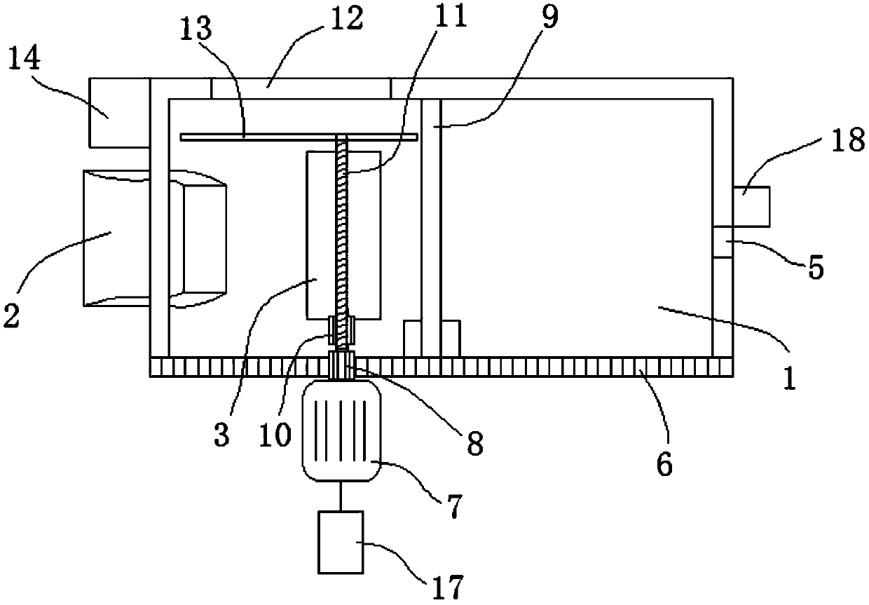
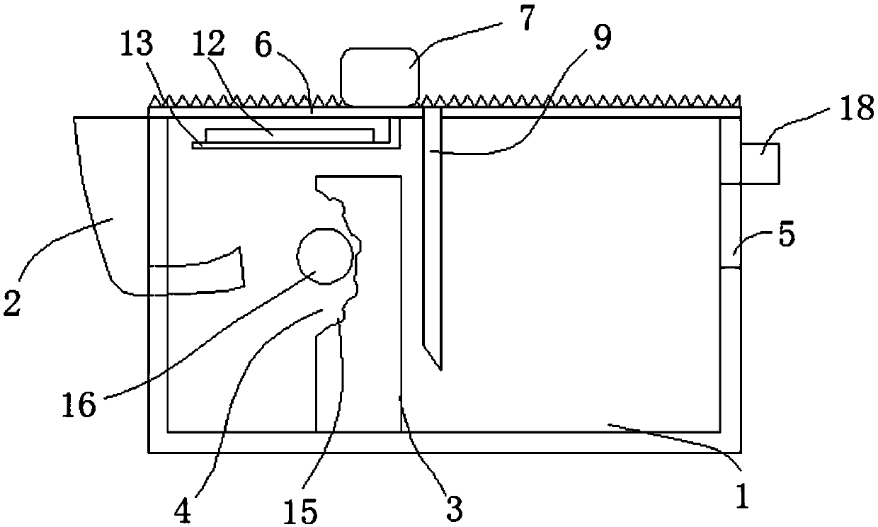
[0025] Such as figure 1 and figure 2 As shown, a smelting water-receiving filter slag tank includes a tank body 1, a water receiving pipe 2 is arranged on an outer wall of the tank body 1, and one end of the water receiving pipe 2 extends into the tank body 1. The side of the tank body 1 close to the water receiving pipe 2 is provided with a redirection device 3 for changing the flow direction of molten water, and the end of the diversion device 3 near the water receiving pipe 2 is provided with an arc groove 4; the tank body 1. A drain port 5 is provided on the side wall away from the water receiving pipe 2;

[0026] The upper end of the side wall of the tank body 1 is provided with a laterally movable rack 6, o...


PUM


Abstract

The invention relates to a smelting water collecting and residue filtering tank which comprises a tank body. A water collecting pipe is arranged on the outer side wall of the tank body. One end of thewater collecting pipe extends into the tank body. The side, close to the water collecting pipe, in the tank body is provided with a flow changing device for changing the flow direction of smelting water. The end, close to the water collecting pipe, of the flow changing device is provided with an arc groove. The side wall, away from the water collecting pipe, of the tank body is provided with a drain outlet. A flow meter is arranged at the drain outlet and detects the flow of the smelting water at the drain outlet to obtain the flow data of the smelting water and display the flow data of the smelting water in real time. Compared with the prior art, residues of the smelting water are filtered away, waste is avoided, the residual removal efficiency of the smelting water is improved, the continuous water injection and flow-uncertain work is met, workers can conveniently know the flow data of the smelting water in real time and adjust the subsequent work, and convenience is improved.

Description

technical field [0001] The invention relates to the technical field of smelting, in particular to a smelting water-receiving filter slag tank. Background technique [0002] Most of the technologies use skimmers to remove the scum on the molten water. The skimmers have the disadvantages of troublesome operation, and often bring good water out, resulting in waste. Another is to install it on the molten water transfer device. The filter plate has the disadvantages that it is difficult to control the scum, and the scum is easy to mix; moreover, in the process of introducing molten water in the prior art, the amount of molten water is uneven, which often causes the molten water in the filter slag tank to overflow, and the scum is not cleaned cleanly; Furthermore, it is impossible to know the outflow of molten water in time, which affects the accuracy of follow-up operations. Contents of the invention [0003] The purpose of the present invention is to provide a smelting water-...

Claims


Application Information

Patent Timeline
IPC IPC(8): B22D43/00
Inventor 吕志雪
Owner 吕志雪
Learn More