
Terminal, charger, charging system and charging method

A charger and charging circuit technology, which is applied in the field of Internet of Vehicles applications, can solve the problems of reducing charging current, inconvenience for users, heating of mobile terminals, etc., and achieve the effect of ensuring normal operation

Inactive Publication Date: 2018-01-12
SHANGHAI YUDE TECH CO LTD
View PDF5 Cites 1 Cited by
  • Summary
  • Abstract
  • Description
  • Claims
  • Application Information

AI Technical Summary

Problems solved by technology

[0003] However, in the process of realizing the present invention, the inventor found that there are some problems in the prior art: in order to meet the needs of users, the current mobile terminals are getting thinner and thinner, so the ornaments of the electronic components on the main board inside the mobile terminal become thinner and thinner. In this case, if a large current is used for charging, the charging chip inside the mobile terminal will be very hot, which will cause the entire mobile terminal to heat up and affect the user experience.
What's more serious is that most mobile terminals, such as mobile phones and tablet computers, will write a thermal mechanism (thermal mechanism) into the internal chip during the manufacturing process. Therefore, when the temperature of the motherboard inside the mobile terminal continues to rise , will automatically limit the processing frequency of the central processing unit and image processor of the terminal, and will reduce the charging current, as well as the rate of data upload and download, which greatly limits the performance of the mobile terminal and brings inconvenience to users

Method used


Image

  • Terminal, charger, charging system and charging method
  • Terminal, charger, charging system and charging method
  • Terminal, charger, charging system and charging method

Examples


Embodiment Construction

[0021] In order to make the object, technical solution and advantages of the present invention clearer, various embodiments of the present invention will be described in detail below in conjunction with the accompanying drawings. However, those of ordinary skill in the art can understand that, in each implementation manner of the present invention, many technical details are provided for readers to better understand the present application. However, even without these technical details and various changes and modifications based on the following implementation modes, the technical solution claimed in this application can also be realized.

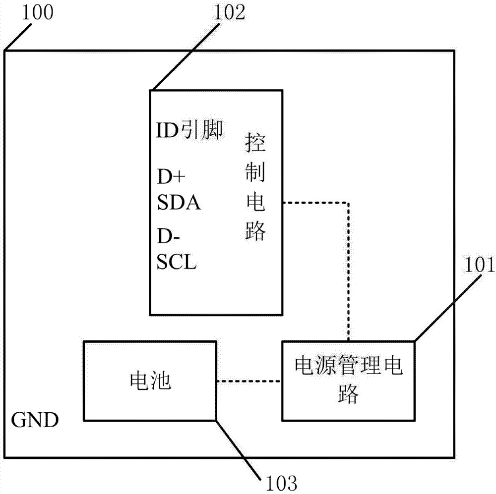
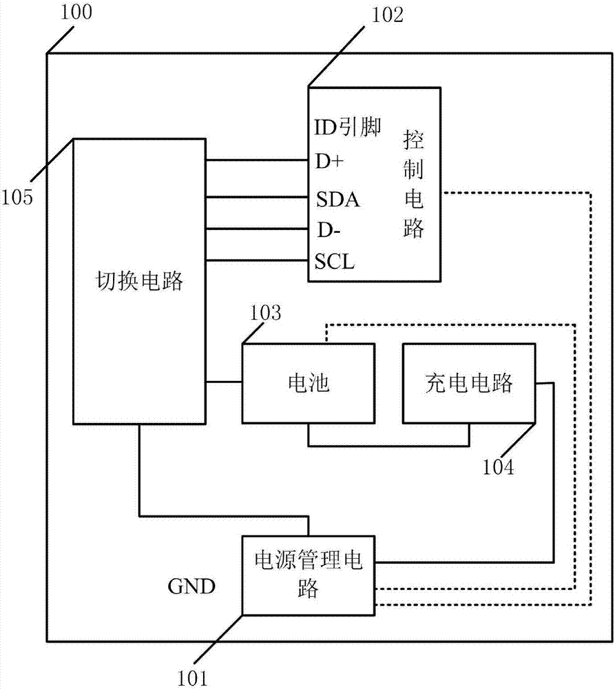
[0022] The first embodiment of the present invention relates to a terminal, the specific structure is as follows figure 1 shown.

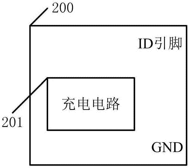
[0023] figure 1 The terminal 100 shown is a terminal used in conjunction with the charger 200 provided in the embodiment of the present invention, such as a mobile phone, a tablet computer, etc., specifically,...


PUM


Abstract

The invention relates to the technical field of electronics, and discloses a terminal, a charger, a charging system and a charging method. The terminal comprises a power management circuit, a controlcircuit and a battery, wherein the control circuit and the battery are electrically connected with the power management circuit; the control circuit comprises an access identification pin, a data terminal and a synchronous serial interface; after the charger is inserted into the terminal, the grounding end of the terminal is connected with the grounding end of the charger, the access identification pin of the control circuit is connected with the access identification pin of the charger, the positive electrode tab of the battery is connected with the output end of the charging circuit of the charger, the synchronous serial interface of the control circuit is connected with the control end of the charging circuit of the charger, and the positive data terminals in the data terminal are connected with the negative data terminals in the data terminal. The provided terminal, charger, charging system and charging method can solve the problem that when the terminal performs large-current charging, the heating is serious.

Description

technical field [0001] The invention relates to the technical field of Internet of Vehicles applications, in particular to a terminal, a charger, a charging system and a charging method. Background technique [0002] With the intelligentization of mobile terminals and the rapid development of mobile application services, portable terminals such as mobile phones have become an indispensable part of people's lives. In order to increase the standby time of mobile terminals, the battery capacity of mobile terminals is also increasing day by day. In order to charge quickly and facilitate users, high-current charging has become a standard configuration for major manufacturers. [0003] However, in the process of realizing the present invention, the inventor found that there are some problems in the prior art: in order to meet the needs of users, the current mobile terminals are getting thinner and thinner, so the ornaments of the electronic components on the main board inside the ...

Claims


Application Information

Patent Timeline
IPC IPC(8): H02J7/00H02J7/04H01M10/44
CPCY02E60/10
Inventor 徐之峰李强
Owner SHANGHAI YUDE TECH CO LTD
Learn More