
A method for forming a channel layer in a channel hole

A channel layer and channel technology, applied in the direction of semiconductor devices, electrical components, circuits, etc., can solve the uneven thickness of the channel layer of polysilicon, the uneven distribution of polysilicon thickness, the influence of channel current, and the electric field intensity of sub-threshold slope Distribution and other electrical properties, to achieve improved performance, uniform gas density, and uniform growth thickness

Active Publication Date: 2019-04-30
YANGTZE MEMORY TECH CO LTD
View PDF5 Cites 0 Cited by
  • Summary
  • Abstract
  • Description
  • Claims
  • Application Information

AI Technical Summary

Problems solved by technology

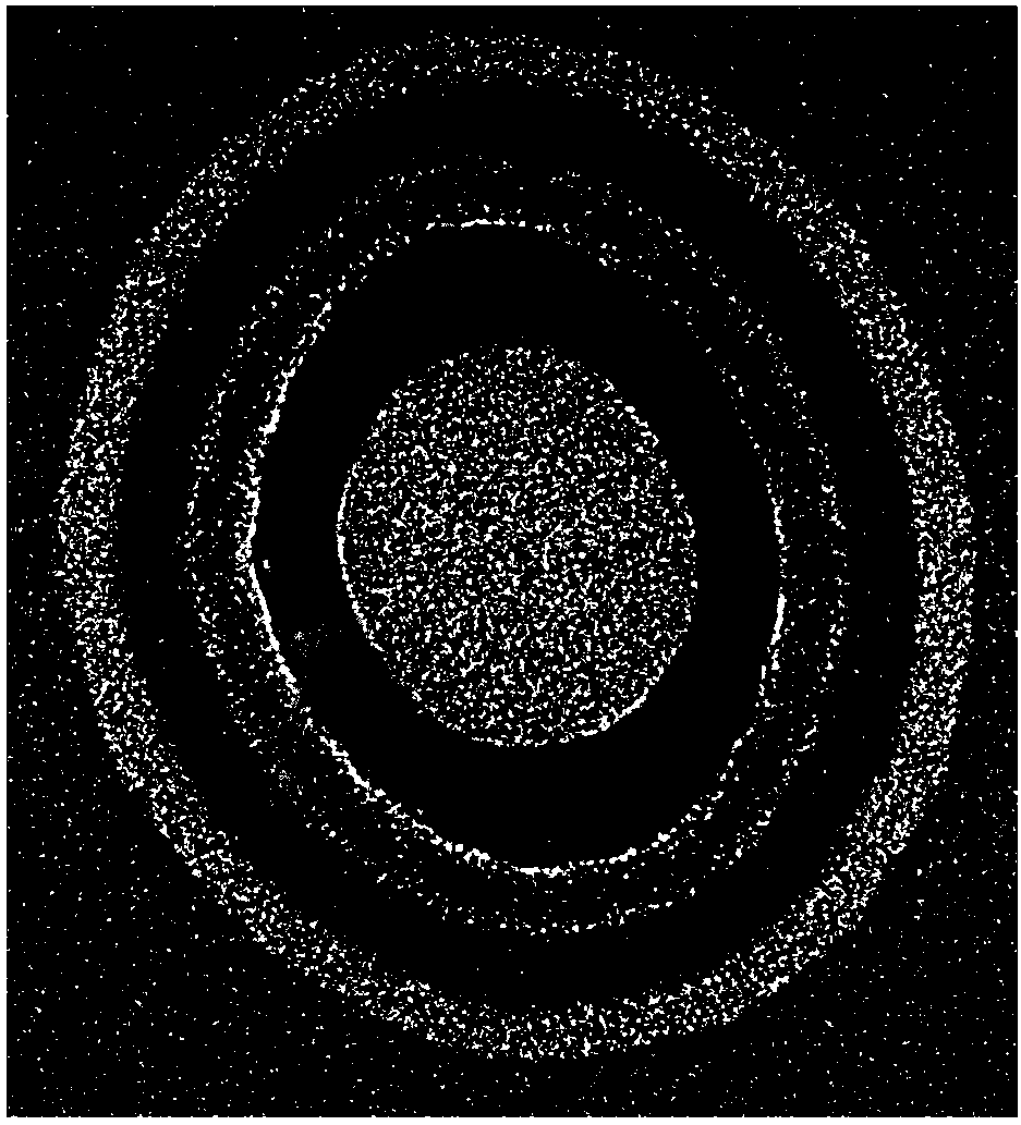
[0004] When etching to form channel holes, it is hoped that the upper and lower parts can form concentric circles, but in the actual process, due to the deep hole depth and the limitation of the process, it is impossible to make the upper and lower concentric circles, and the upper part can basically guarantee concentricity. round, and the lower part is basically elliptical, which causes the thickness non-uniformity of the channel layer of polysilicon when it is formed
refer to figure 1 Shown is the SEM (scanning electron microscope) photograph of the cross-section of the channel hole bottom. It can be seen that the bottom of the channel hole is in the shape of an ellipse, and the thickness distribution of polysilicon is uneven. The thickness of polysilicon in the part of the long axis of the ellipse is The thickness B of the shorter axis part of A is much larger, which will affect the electrical properties such as channel current, subthreshold slope, and electric field intensity distribution, and affect the overall performance of the device

Method used


Image

  • A method for forming a channel layer in a channel hole
  • A method for forming a channel layer in a channel hole
  • A method for forming a channel layer in a channel hole

Examples


Embodiment Construction

[0025] In order to make the above objects, features and advantages of the present invention more comprehensible, specific implementations of the present invention will be described in detail below in conjunction with the accompanying drawings.

[0026] In the following description, a lot of specific details are set forth in order to fully understand the present invention, but the present invention can also be implemented in other ways different from those described here, and those skilled in the art can do without departing from the connotation of the present invention. By analogy, the present invention is therefore not limited to the specific examples disclosed below.

[0027] Secondly, the present invention is described in detail in combination with schematic diagrams. When describing the embodiments of the present invention in detail, for the convenience of explanation, the cross-sectional view showing the device structure will not be partially enlarged according to the gene...


PUM


Abstract

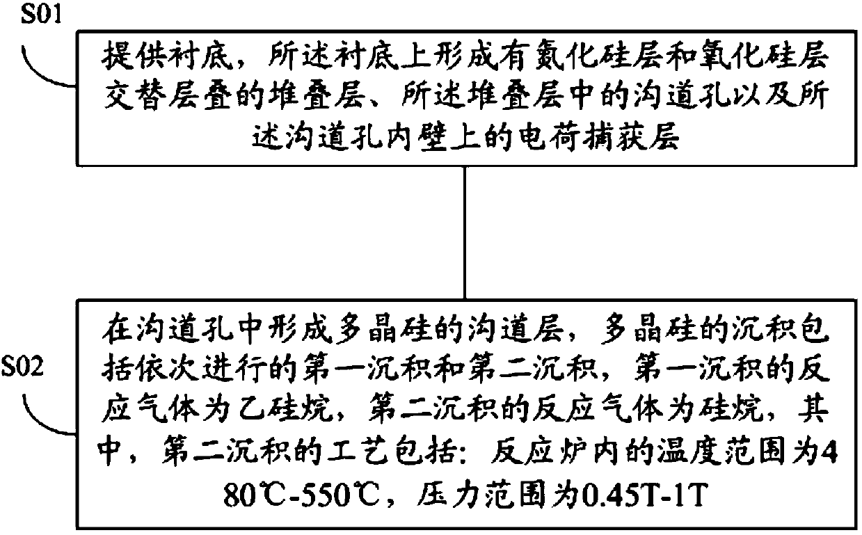
The invention provides a method for forming a channel layer in a channel hole. When forming a channel layer of polysilicon, in the polysilicon deposition process, when the reaction gas is silane, the temperature range in the reaction furnace is 480°C-550°C, and the pressure The range is 0.45T-1T. In this process, the temperature used is lower and the pressure is higher, which increases the amount of gas in the reactor, thereby making the gas density uniform and close to the same surface, thus making the growth thickness uniform and improving device performance.

Description

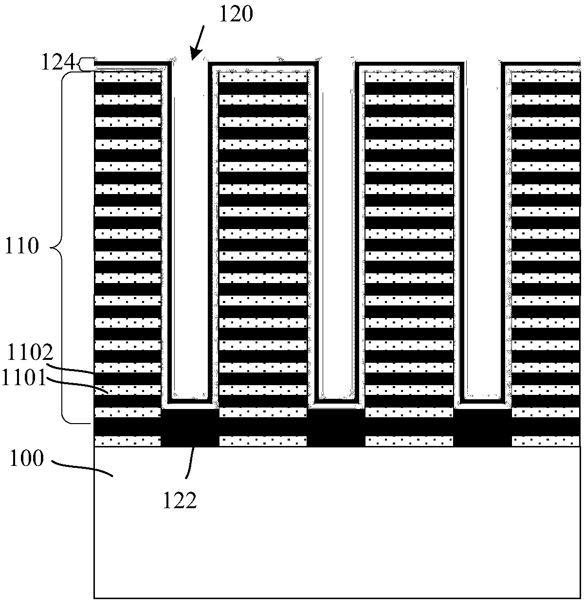
technical field [0001] The invention relates to the field of 3D NAND devices and its manufacture, in particular to a method for forming a channel layer in a channel hole. Background technique [0002] NAND flash memory is a better storage device than hard disk drives, and it has been widely used in electronic products as people pursue non-volatile storage products with low power consumption, light weight and high performance. At present, the planar NAND flash memory is close to the limit of practical expansion. In order to further increase the storage capacity and reduce the storage cost per bit, a 3D NAND memory is proposed. [0003] In the 3D NAND memory structure, a stacked 3D NAND memory structure is realized by vertically stacking multiple layers of data storage units. When forming a 3D NAND memory, first, a silicon nitride (SiN) layer and a silicon oxide (SiO 2 ) layer stacking layer; then, a channel hole (Channel hole) is formed in the stacking layer, and the channe...

Claims


Application Information

Patent Timeline
Patent Type & Authority Patents(China)
IPC IPC(8): H01L27/11563H01L27/11568H01L21/02H10B43/00H10B43/30
Inventor 郁赛华王家友吴关平王秉国吴俊蒲浩李磊
Owner YANGTZE MEMORY TECH CO LTD
Learn More