
Method for monitoring and diagnosing equipment operation states according to vibration algorithm

A technology for equipment operation and equipment, which is applied in the field of monitoring and diagnosing the operation state of equipment using vibration algorithms, can solve the problems such as difficulty in improving the accuracy of signal feature extraction, limited accuracy of signal feature analysis methods, and influence on signal feature extraction accuracy, etc. Achieve the effect of avoiding huge economic losses, avoiding catastrophic accidents, and improving economic and social benefits

Inactive Publication Date: 2018-01-12
WORLD TRANSMISSION TECH TIANJIN SHARE LTD
View PDF4 Cites 19 Cited by
  • Summary
  • Abstract
  • Description
  • Claims
  • Application Information

AI Technical Summary

Problems solved by technology

[0013] However, these existing equipment fault diagnosis methods generally do not use relevant signal preprocessing methods when collecting signals, and directly analyze the collected signals, and the interference such as noise contained therein seriously affects the accuracy of signal feature extraction; The accuracy of the analysis method is limited. Since the current signal characteristic analysis methods are mainly time-domain analysis methods and signal frequency-domain analysis methods based on Fourier transform, the frequency-domain analysis method based on Fourier transform is only suitable for stationary signals. , and the field vibration signal is a non-stationary signal with a lot of noise, which makes it difficult to improve the accuracy of signal feature extraction; the existing technology can only monitor the working conditions of the equipment and realize a simple alarm function, but cannot Analyze the operation trend of the equipment, and it is not possible to analyze the operation trend of the equipment with high precision through the calculation of relevant parameters

Method used


Image

  • Method for monitoring and diagnosing equipment operation states according to vibration algorithm

Examples


Embodiment Construction

[0025] Below in conjunction with accompanying drawing and embodiment the present invention will be further described:

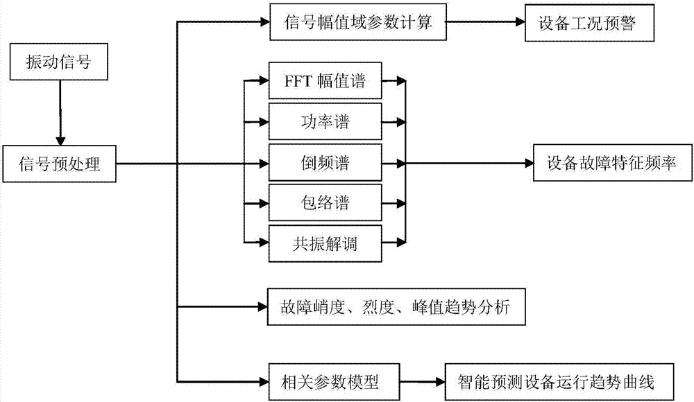
[0026] Such as figure 1 As shown, a method for monitoring and diagnosing the operating state of equipment using a vibration algorithm is characterized in that it includes the following process:

[0027] ① Perform signal preprocessing on the collected vibration signals of the equipment. Since the collected vibration signals inevitably contain noise, firstly perform noise reduction preprocessing on the collected vibration signals to reduce the interference of noise on the signal and improve the signal-to-noise According to the actual operation of the equipment, select the appropriate IIR filter for filtering; the filter forms include: Butterworth filter, Chebyshev filter, inverse Chebyshev filter, elliptic filter and Bessel filter ;

[0028] ②Calculate the amplitude field parameters of the preprocessed signal to realize the early warning of the equipment work...


PUM


Abstract

The invention discloses a method for monitoring and diagnosing equipment operation states according to a vibration algorithm. By the method, the equipment operation states can be monitored, time domains and frequency domains of vibration signals of equipment and operation trends of the equipment can be analyzed, residual service life of the equipment can be predicated according to an intelligent learning algorithm, proper signal collection strategies can be selected according to actual conditions to collect the vibration signals, change conditions of the vibration signals can be monitored, some related technical parameters can be monitored and warned, time domain waveforms of the vibration signals can be monitored, the equipment operation states can be diagnosed according to related features of the signals through signal analysis, and fault positions and fault types of the equipment can be determined. The method plays a large role in reducing maintenance cost and production cost and improving economical and social benefits, and has significance in avoiding huge economic losses and catastrophic accidents.

Description

technical field [0001] The invention relates to the field of equipment fault diagnosis, in particular to a method for monitoring and diagnosing the operating state of equipment by using a vibration algorithm. Background technique [0002] The production equipment in modern enterprises is increasingly large-scale, continuous, high-speed and automated, which has also become the main feature of modern large-scale enterprise production. The structure and composition of the equipment are very complex, the production scale is very large, and the connection between various parts is also particularly close. Although this helps to increase productivity, reduce product production costs and improve product quality, on the other hand, the loss caused by downtime due to mechanical equipment failure has greatly increased. Modern large-scale production industries, such as petroleum, petrochemical, chemical, electric power, and steel, all adopt single-machine, full-load, and continuous pro...

Claims


Application Information

Patent Timeline
Patent Type & Authority Applications(China)
IPC IPC(8): G01M13/00
Inventor 胡炜
Owner WORLD TRANSMISSION TECH TIANJIN SHARE LTD
Learn More