Liquid crystal display screen main pressing device

A technology of liquid crystal display screen and local pressure device, which is applied in nonlinear optics, instruments, optics, etc., can solve the problems of the applicability of the suction mechanism, the uneven pressing pressure, and the placement accuracy, and improve the adjustable degree of freedom. , High camera positioning accuracy, reducing the effect of pressing errors

Pending Publication Date: 2018-01-09
苏州富强加能精机有限公司
View PDF0 Cites 2 Cited by
  • Summary
  • Abstract
  • Description
  • Claims
  • Application Information

AI Technical Summary

Problems solved by technology

[0007] 1) Due to the thin thickness of the Driver IC and PCB, a slight deviation in the parallelism between the indenter plane and the lamination platform will lead to uneven lamination pressure, which makes it easy to fall off and glue open after lamination;
[0008] 2) It is difficult to quickly and effectively remove the product to be pressed from the conveying guide rail, resulting in low pressing efficiency;
[0009] 3) There is no mechanism for thermal insulation and pressing protection of the surface of the Driver IC or PCB during the pressing process, which is likely to cause burns or crush damage to the surface of the Driver IC or PCB during the pressing process;
[0010] 4) Due to the limitation of the degree of freedom, it cannot adapt to Driver ICs of different sizes and specifications, which has a certain impact on the applicability of the suction mechanism. In addition, the placement accuracy of the existing suction mechanism is revealed, resulting in the Driver IC being pressed A large error occurs in the process, which affects the yield rate;
[0011] 5) For different lamination requirements and Driver IC or PCB size models, it is often impossible or inconvenient to make corresponding position adjustments for the camera used for alignment, which makes the camera unable to focus accurately and affects the positioning accuracy of the photo

Method used


Image

  • Liquid crystal display screen main pressing device
  • Liquid crystal display screen main pressing device
  • Liquid crystal display screen main pressing device

Examples


Embodiment Construction

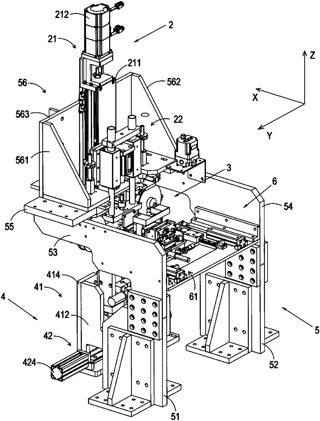
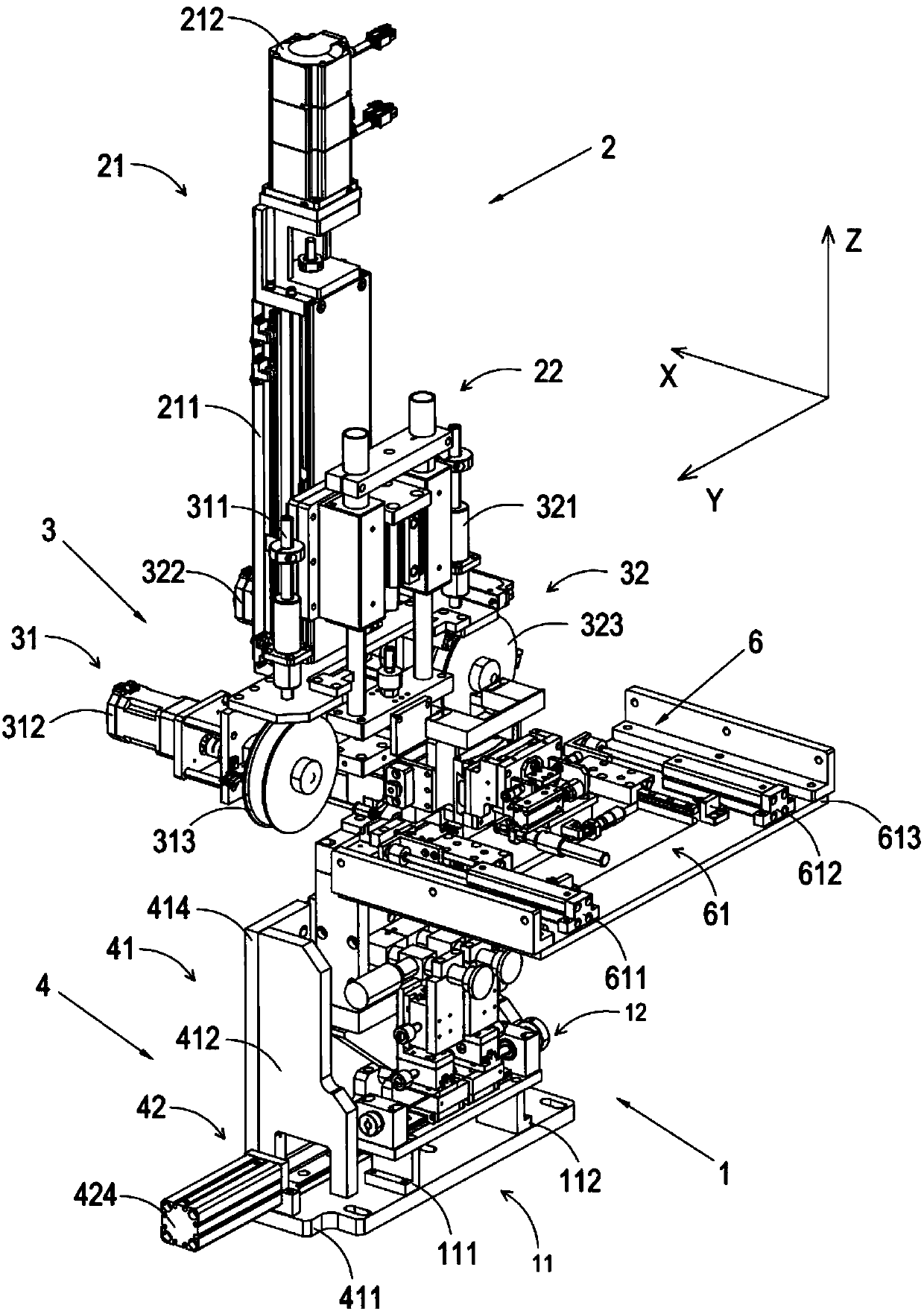
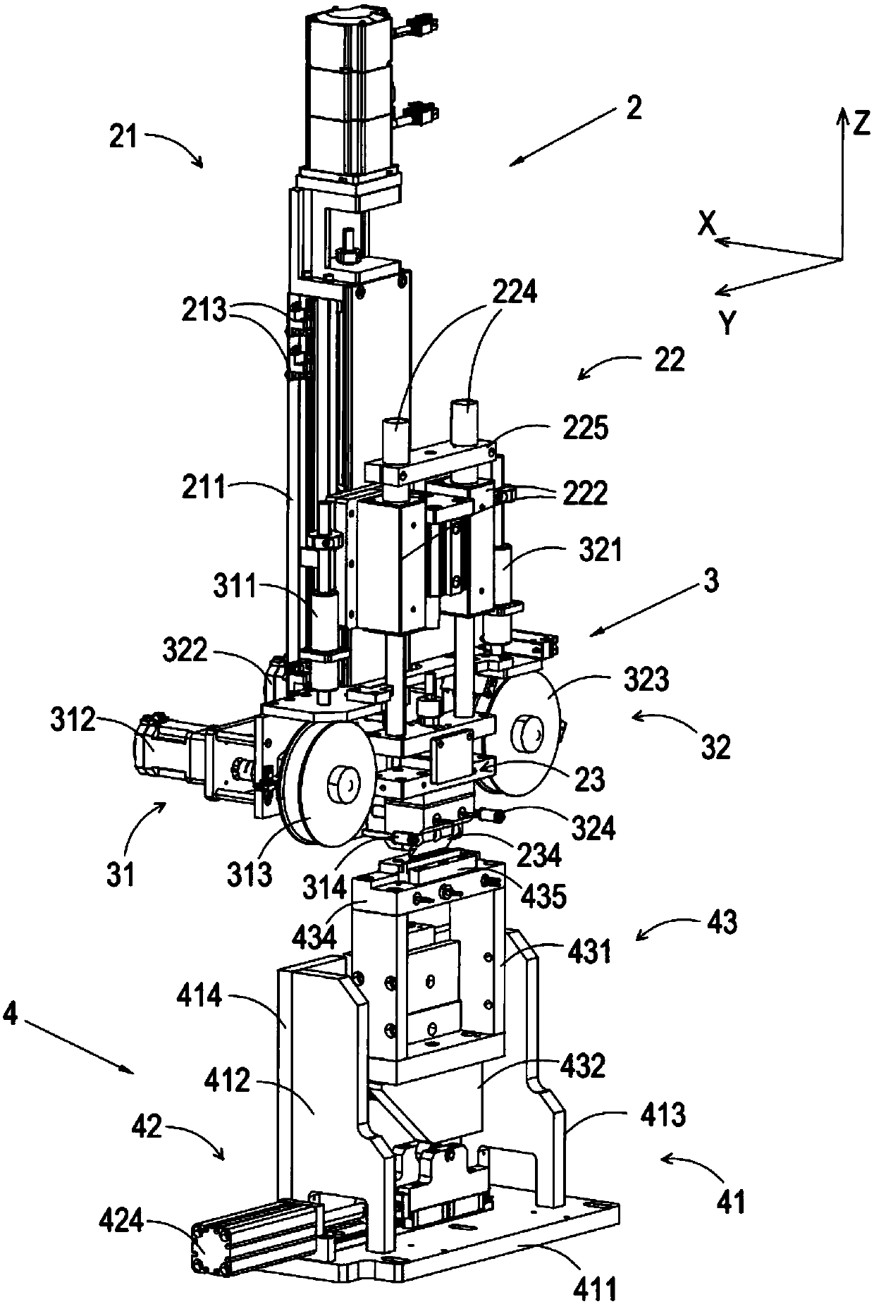
[0058] The present invention will be further described in detail below in conjunction with the accompanying drawings, and the aforementioned and other objects, features, aspects and advantages of the present invention will become more apparent, so that those skilled in the art can implement them with reference to the description. In the drawings, the shapes and dimensions may be exaggerated for clarity, and the same reference numerals will be used throughout to designate the same or like parts. In the following description, terms such as center, thickness, height, length, front, back, rear, left, right, top, bottom, upper, lower, etc. are based on the orientation or positional relationship shown in the drawings. In particular, "height" corresponds to the dimension from top to bottom, "width" corresponds to the dimension from left to right, and "depth" corresponds to the dimension from front to back. These relative terms are for convenience of description and are generally not ...


PUM


Abstract

The invention discloses a liquid crystal display screen main pressing device. The device comprises a rack with a certain internal space, a main pressing mechanism and a sucking mechanism, and the mainpressing mechanism and the sucking mechanism are arranged on the rack; the sucking mechanism is located under the main pressing mechanism and is baised on one side of the main pressing mechanism, anda lifting platform is arranged under the main pressing mechanism. The device is high in photographing positioning precision, and stable and uniform pressing pressure can be provided, so that a pressed IC is not likely to unglue and fall off, and the quality of a liquid crystal display screen is improved; a to-be-pressed product on a conveying guide rail can be conveniently and rapidly jacked up,and the pressing efficiency is improved; thermal protection and buffering protection can be provided for the surface of a Driver IC or a PCB in the main pressing process; the adjustable freedom degreecan be improved to adapt to to-be-sucked pieces in different specifications and sizes, the to-be-sucked pieces can be precisely placed, pressing errors can be reduced, and the yield is increased.

Description

technical field [0001] The invention relates to the field of liquid crystal display screens, in particular to a pressure device for liquid crystal display screens. Background technique [0002] LCD (Liquid Crystal Display) is a flat and ultra-thin display device, which consists of a certain number of color or black and white pixels, placed in front of the light source or reflective surface. [0003] The display principle of LCD is to fill the liquid crystal material between two parallel plates, and change the alignment of molecules inside the liquid crystal material through voltage, so as to achieve the purpose of shading and light transmission to display images of different shades and well-arranged patterns. And as long as a filter layer of three primary colors is added between two flat plates, color images can be displayed. At present, monochrome LCD has almost withdrawn from the notebook computer market, while color LCD continues to develop. Color LCD is mainly divided ...

Claims


Application Information

Patent Timeline
IPC IPC(8): G02F1/13
Inventor 张天恩吴加富蔡建明
Owner 苏州富强加能精机有限公司
Why Eureka
Try Eureka