Cages for crankshaft bearing assemblies

A bearing assembly and cage technology, applied in the field of crankshaft bearing assemblies, connecting rods and/or main shaft bearing assemblies of crankshafts, to avoid lubricant accumulation, reduce motion, and reduce friction

Active Publication Date: 2021-09-28
AB SKF
View PDF7 Cites 0 Cited by
  • Summary
  • Abstract
  • Description
  • Claims
  • Application Information

AI Technical Summary

Problems solved by technology

[0003] However, a disadvantage of this prior art is that, while lubricant can be guided to the bearing, a lubricant change is only possible to a limited extent, since at least some of the lubricant remains stationary in the bearing

Method used


Image

  • Cages for crankshaft bearing assemblies
  • Cages for crankshaft bearing assemblies
  • Cages for crankshaft bearing assemblies

Examples


Embodiment Construction

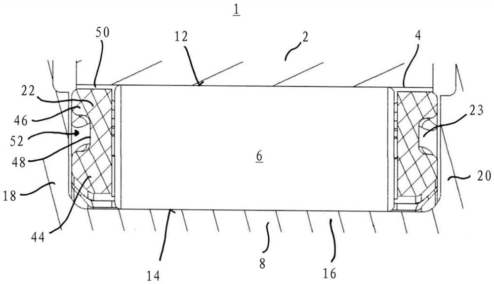
[0029] figure 1A perspective section through a rolling element bearing assembly 1 is shown, which in the shown case is designed as a crankshaft bearing assembly. as from figure 1 As can be seen in the figure, a rolling element bearing 6 is arranged in a connecting rod eye 4 of the connecting rod 2 or in the housing 4 for the crankshaft. The rolling element bearing 6 ensures the rolling of the connecting rod 2 or housing 4 along the crankshaft 8 . here, as from figure 1 As can be seen in the rolling element bearing assembly 6, the outer raceway 12 on which the rolling elements 10 roll is formed above the connecting rod bore or housing 4, while the inner raceway 14 is shown on the crankpin 16 of the crankshaft 8 above. The crankpin 16 is in turn arranged between two crankshaft cheeks 18 , 20 which extend axially beyond the outer race surface 12 of the connecting rod bore 4 .

[0030] The installation space available for the rolling element bearing 6 is limited by the height...


PUM


Abstract

A rolling element bearing assembly includes a radially inner race surface and a radially outer race surface disposed spaced apart from each other with rolling elements disposed therebetween that roll on the race surfaces and that are received in a In a cage of at least two side rings spaced apart from each other by a bridge, wherein the bridges form between themselves recesses that receive the rolling elements spaced apart from each other and guide them, and wherein the radial An inner race surface is provided on a first part and a radially outer race surface is provided on a second part, wherein the first and second parts are rotatably supported relative to each other, and wherein, furthermore, the rolling element bearing assembly shaft The upward direction is bounded by a side wall of at least one of the parts, the side wall extending at least partially radially beyond the raceway surface, wherein at least one side ring of the cage is configured at least partially corrugated. A bearing cage for such a rolling element bearing assembly is also disclosed.

Description

technical field [0001] The invention relates to a rolling element bearing assembly, in particular for a crankshaft bearing assembly, in particular for a connecting rod and / or main shaft bearing assembly of a crankshaft. Background technique [0002] Plain bearings and / or rolling element bearings are commonly used in crankshaft bearing assemblies. The pin of the crankshaft is bounded here by two crankshaft sides, so that the bearing assembly is not only bounded on its radially inner diameter and radially outer race surface, but also axially bounded by the crankshaft cheek. Among other things, with roller bearings, this limited installation space can lead to problems with lubricant supply. Thus, for example, the installation space allows only a limited possibility of supplying the required lubricating film in the rolling element bearings from the inside outwards via the housing raceways into the motor housing which receives the crankshaft. To solve this problem, it has been ...

Claims


Application Information

Patent Timeline
Patent Type & Authority Patents(China)
IPC IPC(8): F16C33/46F16C33/56F16C33/66F16C9/02
CPCF16C9/00F16C19/26F16C33/516F16C33/585F16C33/6681F16C2360/22F16C9/04
Inventor F.迈耶J.韦格莱因
Owner AB SKF
Why Eureka
Try Eureka