
Ballasting device and installation method for tr components

A component and tableting technology, applied in the field of TR component ballast devices, can solve the problems of low product yield, excessive oxidation slag, slow production speed, etc., and achieve the effect of reducing welding void rate, saving production cost, and improving production efficiency

Active Publication Date: 2019-10-25
成都雷电微力科技股份有限公司
View PDF7 Cites 0 Cited by
  • Summary
  • Abstract
  • Description
  • Claims
  • Application Information

AI Technical Summary

Problems solved by technology

[0006] The purpose of the present invention is to solve the problem of using vacuum eutectic welding. The operation and calculation parameters are very complicated. Using manual tweezers for eutectic welding can easily generate oxide film, resulting in a large void rate and a lot of oxidized dross, and the device will fail early. The force applied on the chip can easily cause chip chipping, edge chipping, inaccurate alignment, and asynchronous pressure loading. It is difficult to complete the installation of circuit chips and TR components at the same time. The eutectic of multiple TR components is difficult, and the degree of human participation is high. , for the problems of high manual operation requirements, low product yield, slow production speed, and difficulty in mass production, thus providing a TR component ballast device and installation method

Method used


Image

  • Ballasting device and installation method for tr components
  • Ballasting device and installation method for tr components
  • Ballasting device and installation method for tr components

Examples


Embodiment 1

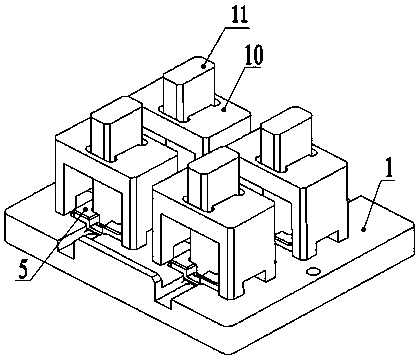
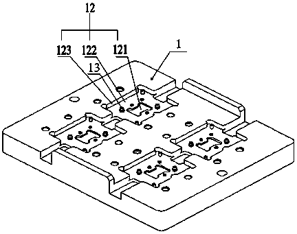
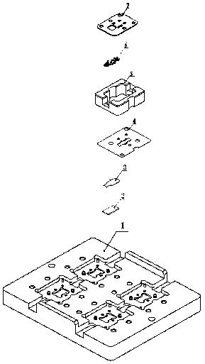
[0067] as attached figure 1 to attach Figure 17 In this embodiment shown, a TR component ballasting device and installation method include a base 1, a heat bearing plate 2, a forming solder piece 3, a positioning steel piece 4, an anti-loose pressing block 5, a TR component 6, a chip pressing piece 7, and a chip Counterweight pressing block 8, displacement counterweight 9, radio frequency microstrip counterweight guide plate 10, radio frequency microstrip counterweight 11, eutectic groove 12, substrate 121, positioning surface 122, limit step 123, screw 13 , high-density multi-chip and heat sink carrier board vacuum eutectic welding tooling, use the tooling to ensure that 3 devices with different thicknesses (chips, row capacitors and microstrips, the structural size is less than 2mm, and the thickness is above 0.1) on the TR module 6, By positioning the device with the tooling and separately pressing the devices with different heights, it can be eutectic on a small heat sin...

Embodiment 2

[0077] as attached figure 1 to attach Figure 17, which shows a TR component ballasting device and installation method in this embodiment. The base 1 with several eutectics 12 is molded at one time, and each eutectic groove 12 includes a substrate 121, a positioning surface 122 and a limiting step 123, Therefore, multiple TR components 6 can be vacuum eutectically welded at the same time, greatly improving production efficiency and saving production costs. By positioning the positioning steel sheet 4 and the screw 13 of the chip pressing sheet 7 and setting the anti-loosening pressure block 5 on the positioning steel sheet 4, In order to ensure that the positioning steel sheet 4 is not deformed and shake up and down to improve the alignment accuracy of the TR assembly 6 in the positioning steel sheet 4 during eutectic welding, the chip counterweight pressing block 8 is placed on the chip pressing sheet 7 to realize chip processing. Pressurize, through the through hole of the ...


PUM


Abstract

The invention relates to the field of microwave, in particular to a TR module pressing and carrying device and an installation method thereof. The TR module pressing and carrying device comprises a base, wherein a plurality of eutectic grooves are formed in the base, each eutectic groove comprises a substrate, a positioning surface and a limitation step, a heat sink carrying plate and a formationwelding sheet are arranged in the substrate, the positioning surface is used for placing a positioning steel sheet, the limitation step is used for arranging a loosen-prevention press block, the loosen-prevention press block is used for preventing the positioning steel sheet from being deformed and shaking, a chip counterweight press block is arranged on the loose-prevention press block, a capacity discharging via hole and a radio frequency microstrip via hole are respectively formed in a chip press sheet coverage capacity discharging region and a radio frequency microstrip region, and a capacity discharging counterweight piece and a radio frequency microstrip counterweight piece are respectively arranged in the capacity discharging via hole and the radio frequency microstrip via hole. Thedevice is simple in structure and is convenient to operate, a plurality of TR modules can be eutectically welded in one time, and the welding void rate of the TR module is reduced.

Description

technical field [0001] The invention relates to the field of microwave technology, in particular to a TR component ballasting device and an installation method. Background technique [0002] In China, the microwave field is in a stage of rapid development, and the technical core of its field is still TR components. TR components include TR components including chips, radio frequency microstrips, and capacitors. The electrical properties of TR components are not only related to chip performance and its matching chain. In addition to being closely related to the circuit, it is also related to the alignment accuracy of each device and the eutectic void rate in the packaging process. For high-power TR components, the void rate of chip soldering during the eutectic packaging process will directly affect its life and TR components. Overall performance, at this stage, eutectic welding of TR components often adopts two welding methods: manual tweezers eutectic welding and vacuum eut...

Claims


Application Information

Patent Timeline
Patent Type & Authority Patents(China)
IPC IPC(8): H05K13/04
Inventor 廖洁王正海
Owner 成都雷电微力科技股份有限公司
Learn More