
Positioning device and method for hydrophobicity detection of composite insulator based on unmanned aerial vehicle

A technology of composite insulators and positioning devices, which is applied in the directions of measuring devices, launching devices, three-dimensional position/channel control, etc., and can solve problems such as difficult to accurately control water spray heads and composite insulators

Inactive Publication Date: 2018-01-05
国网河南省电力公司超高压公司 +1
View PDF2 Cites 9 Cited by
  • Summary
  • Abstract
  • Description
  • Claims
  • Application Information

AI Technical Summary

Problems solved by technology

However, this invention still has the problem that it is difficult to accurately control the distance between the water spray head and the composite insulator to be 25cm

Method used


Image

  • Positioning device and method for hydrophobicity detection of composite insulator based on unmanned aerial vehicle
  • Positioning device and method for hydrophobicity detection of composite insulator based on unmanned aerial vehicle
  • Positioning device and method for hydrophobicity detection of composite insulator based on unmanned aerial vehicle

Examples


Embodiment 1

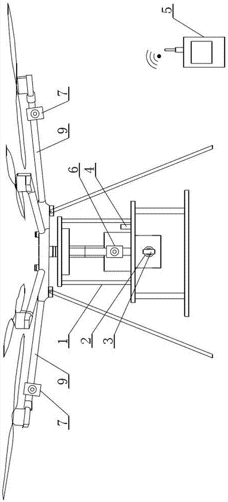
[0052] like figure 1 , figure 2 and image 3 As shown, the positioning device based on the UAV-based composite insulator hydrophobicity detection includes a multi-rotor UAV body 1, and a water spray insulation rod 2 arranged at the bottom of the multi-rotor UAV body 1 is arranged on the nozzle. The water spray head 3 at the front end of the water insulating rod 2, the positioning module arranged on the multi-rotor UAV body 1, the image acquisition module 4 arranged on the multi-rotor UAV body 1, and the An image monitoring module 5 controlled by an operator;

[0053] The positioning module includes a first positioning laser transmitter 6 and two second positioning laser transmitters 7, the first positioning laser transmitter 6 is installed on the front side of the multi-rotor UAV body 1 and is located in the Directly above the water spray insulation rod 2, the first positioning laser transmitter 6 is used for rough positioning, and the laser beam emitted by the first posit...

Embodiment 2

[0067] The difference from Embodiment 1 is that the image acquisition module 4 includes an image acquisition camera and an image return transmitter.

[0068] The image monitoring module 5 includes an image return receiver and an image monitor, the image return receiver is used to receive the image signal sent by the image return transmitter, and the image monitor is used to display the image return The image signal received by the receiver.

[0069] The water spray head is made of aluminum alloy, and the aluminum alloy is made of the following components in mass percentage:

[0070] Mg: 2.8%;

[0071] Si: 4.2%;

[0072] Mn: 0.28%;

[0073] Cr: 0.16%;

[0074] Zr: 0.23%;

[0075] Ti: 0.38%;

[0076] Yb: 0.25%;

[0077] The balance is Al and impurities with a content of ≤0.05%.

[0078] In this embodiment, the image monitor is an LCD monitor, and it is obvious that an LED monitor can have the same effect.

[0079] In this embodiment, the image acquisition module include...

Embodiment 3

[0081] It differs from Embodiment 2 in that: the image monitor is an LCD monitor.

[0082] The water spray head is made of aluminum alloy, and the aluminum alloy is made of the following components in mass percentage:

[0083] Mg: 2.2%;

[0084] Si: 3.6%;

[0085] Mn: 0.23%;

[0086] Cr: 0.12%;

[0087] Zr: 0.20%;

[0088] Ti: 0.36%;

[0089] Yb: 0.18%;

[0090] The balance is Al and impurities with a content of ≤0.05%.


PUM

PropertyMeasurementUnit
Tensile strengthaaaaaaaaaa
Yield strengthaaaaaaaaaa

Abstract

The invention discloses a positioning device and method for detecting the hydrophobicity of a composite insulator based on a drone, wherein the positioning device for detecting the hydrophobicity of a composite insulator based on a drone includes a multi-rotor drone body, which is arranged on the multi-rotor drone body The water spray insulating rod at the bottom, the water spray head arranged at the front end of the water spray insulating rod, the positioning module arranged on the body of the multi-rotor UAV, the image acquisition module arranged on the body of the multi-rotor UAV, and the And the image monitoring module controlled by the operator; the positioning module includes a first positioning laser emitter and two second positioning laser emitters. The laser beams emitted by the first positioning laser transmitter and the two second positioning laser transmitters form a spot at the intersection position, so that the image monitoring module can be used to clearly observe the position of the spot on the ground, and combine it with the detected spot by judging The insulator coincides to realize precise control of the distance between the sprinkler head and the composite insulator.

Description

technical field [0001] The invention relates to the technical field of electric power detection, in particular to a positioning device and method for detecting the hydrophobicity of composite insulators based on an unmanned aerial vehicle. Background technique [0002] Composite insulators in transmission lines are often polluted by dirt such as dust. When the climate is relatively humid, a large amount of dirt is attached to the surface of composite insulators, resulting in a decrease in flashover voltage, and even flashovers will occur at rated operating voltages, causing the power grid to safe operation is greatly affected. Therefore, it is necessary to check the contamination on the surface of composite insulators of transmission lines and remove the contamination. The study found that there is a certain correlation between the dirt on the surface of the composite insulator and its hydrophobicity, so the degree of dirt attached to the surface of the composite insulator ...

Claims


Application Information

Patent Timeline
IPC IPC(8): G05D1/10B64D1/18G01N13/00
Inventor 沈辉彭勇李忠民张建辉陶留海石生智高嵩刘雁南刘阔孙恵涛郭栋崔磊李学奎刘琦孙超秦岭陈鹏赵龙杨东辉樊建军
Owner 国网河南省电力公司超高压公司
Learn More