
Transmission, transmission actuating mechanism and positioning locking device for shift fork shaft

A control mechanism and shifting fork shaft technology, applied in mechanical control devices, transmission control, instruments, etc., can solve problems such as damage to the transmission, a large number of parts, increase the difficulty of layout and cost, and reduce the number of parts and reduce costs. The effect of layout difficulty and cost

Active Publication Date: 2019-02-15
蜂巢传动系统(江苏)有限公司
View PDF7 Cites 0 Cited by
  • Summary
  • Abstract
  • Description
  • Claims
  • Application Information

AI Technical Summary

Problems solved by technology

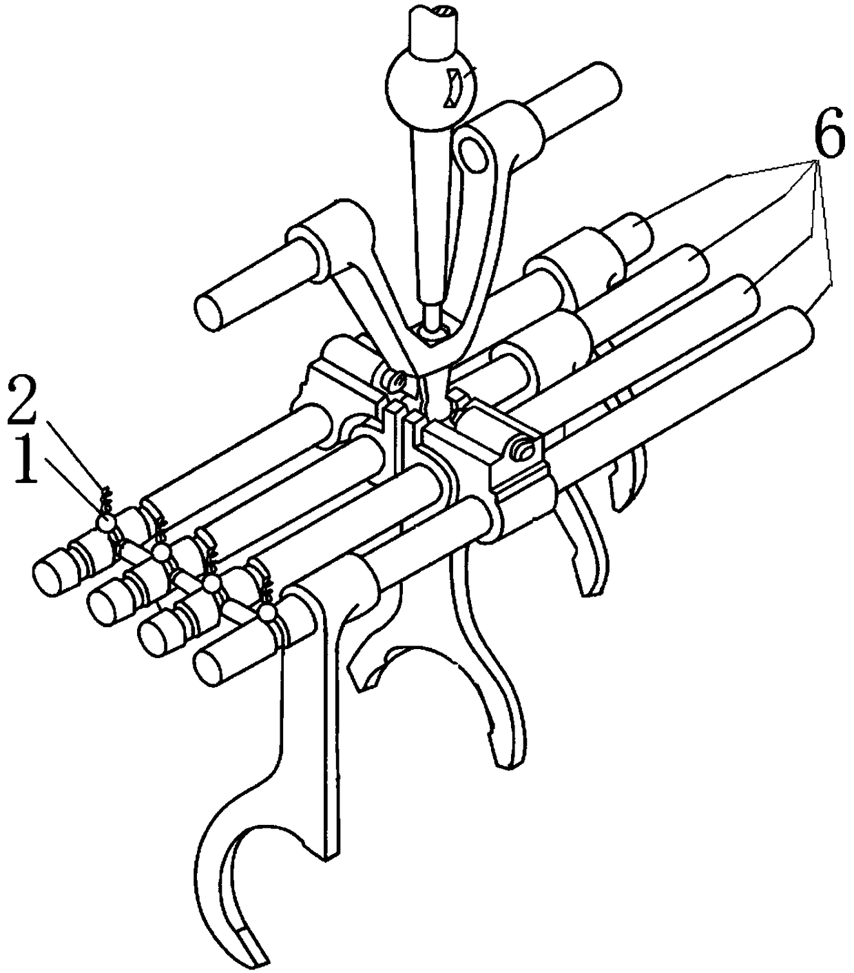
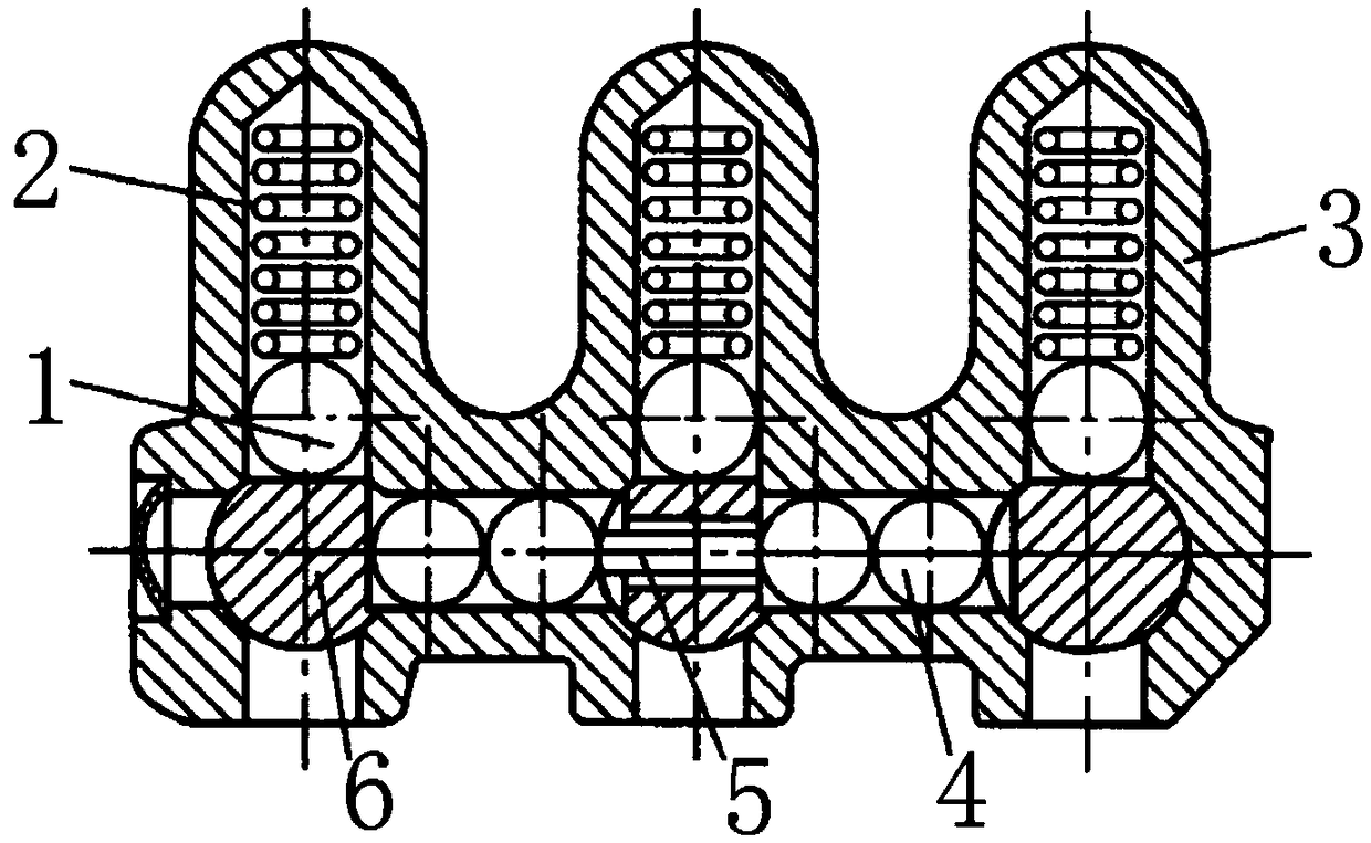
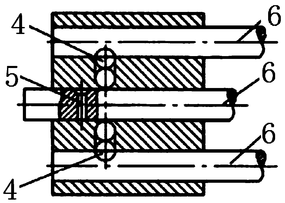
[0006] There are various disadvantages in the above-mentioned existing positioning locking device, for example, it is necessary to process deep holes for accommodating the self-locking steel ball 1 and the self-locking spring 2 on the transmission cover 3, which easily leads to poor sealing of the gearbox; The lock is completed by two relatively independent devices, and the number of parts is large, which increases the difficulty and cost of layout
With the development requirements of automation and integration, for the dual-clutch automatic transmission (DCT), there is no interlock device, which may easily cause problems such as wrong gearing and damage the transmission.

Method used


Image

  • Transmission, transmission actuating mechanism and positioning locking device for shift fork shaft
  • Transmission, transmission actuating mechanism and positioning locking device for shift fork shaft
  • Transmission, transmission actuating mechanism and positioning locking device for shift fork shaft

Examples


Embodiment Construction

[0034] It should be noted that the embodiments of the present invention and the features of the embodiments may be combined with each other under the condition of no conflict.

[0035] The present invention will be described in detail below with reference to the accompanying drawings and in conjunction with the embodiments.

[0036] refer to Figure 4 and Figure 5 As shown, according to a preferred embodiment of the positioning and locking device for the fork shaft of the present invention, the self-locking and / or interlocking of the fork shaft 6 can be realized. The positioning locking device includes a torsion spring 7 and a pair of interlocking discs 8 . Wherein, the pair of interlocking discs 8 are matched with each other, and have a tendency to rotate relative to each other under the action of the torsion spring 7 . For example, combining 6A to 6D As shown, between the first interlocking disc 8a and the second interlocking disc 8b 6A to 6D During the relative rota...


PUM


Abstract

The invention relates to the field of transmissions, and provides a transmission, a transmission operation mechanism and a positioning locking device for shift shafts. The positioning locking device comprises a torsion spring and at least one pair of interlocking discs which are arranged in a matched mode and have the relative rotation tendency under the effect of the torsion spring. The pair of interlocking discs is provided with locking parts and torsion spring connection portions used for supporting or being connected with the end of the torsion spring. In the installation state, the torsion spring is compressed, acts on the torsion spring connection portion to enable the interlocking discs to have the relative rotation tendency, and therefore the locking parts have the tendency of being away from each other so as to abut against the corresponding shift shafts. According to the positioning locking device, the torsion spring can be used for driving the locking parts to lock the shiftshafts, deep holes for containing self-locking steel balls and self-locking springs do not need to be formed in a transmission cover, and sealing performance of a gearbox is prevented from being affected.

Description

technical field [0001] The invention relates to the technical field of transmissions, in particular to a positioning locking device for a shift fork shaft. On this basis, the present invention also relates to a transmission operating mechanism having the positioning locking device and a transmission including the transmission operating mechanism. Background technique [0002] The transmission is an important part of the vehicle chassis drive system. The driver engages different gears by shifting the gear lever, so as to adapt to the frequently changing driving conditions and make the engine work under favorable conditions. Taking a stepped transmission as an example, in order to output different speeds and torques, there are multiple pairs of meshing gear sets in the gearbox. By selecting meshing gears with different transmission ratios on the transmission path, different output speeds and torques can be obtained. . [0003] In order to ensure that the transmission can wo...

Claims


Application Information

Patent Timeline
Patent Type & Authority Patents(China)
IPC IPC(8): F16H63/34F16H63/32
Inventor 樊立桃何岩青郭伟光张和平田广召
Owner 蜂巢传动系统(江苏)有限公司
Learn More