Electric brake

A technology of electric brakes and brake discs, applied in the types of brakes, axial brakes, brake actuators, etc., can solve the problems of difficulty in determining whether the braking force of the friction pads is sufficient, the braking response speed is slow, and the braking force is insufficient. , to achieve the effect of improving braking effect, fast response speed and uniform braking force

Pending Publication Date: 2018-01-05
LONGZHONG HLDG GRP
View PDF1 Cites 4 Cited by
  • Summary
  • Abstract
  • Description
  • Claims
  • Application Information

AI Technical Summary

Problems solved by technology

[0004] However, in this electric brake, only a brake nut is driven by a motor to press a friction plate on the brake disc to achieve braking. Because the friction plate is not directly connected with the brake nut, and the brake disc is Circumferential rotation will occur, and when the brake nut pushes the friction plate against the brake disc, as the brake disc rotates, the friction plate will easily deflect around the action point of the brake nut, thus causing the friction plate to In the case of eccentric wear, the braking effect is poor; and it is difficult to determine whether the braking force of the friction plate is sufficient when the electric brake is braking. After long-term use and wear of the friction plate, insufficient braking force is prone to occur, resulting in poor braking effect and poor braking response. Slow speed or even brake failure

Method used


Image

  • Electric brake
  • Electric brake
  • Electric brake

Examples


Embodiment Construction

[0032] The following are specific embodiments of the present invention and in conjunction with the accompanying drawings, the technical solutions of the present invention are further described, but the present invention is not limited to these embodiments.

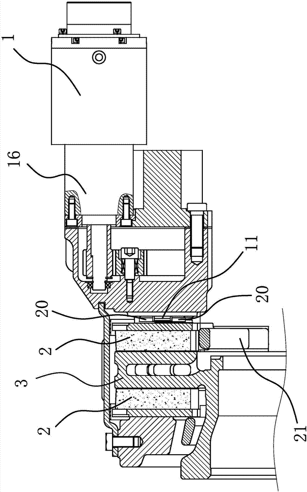
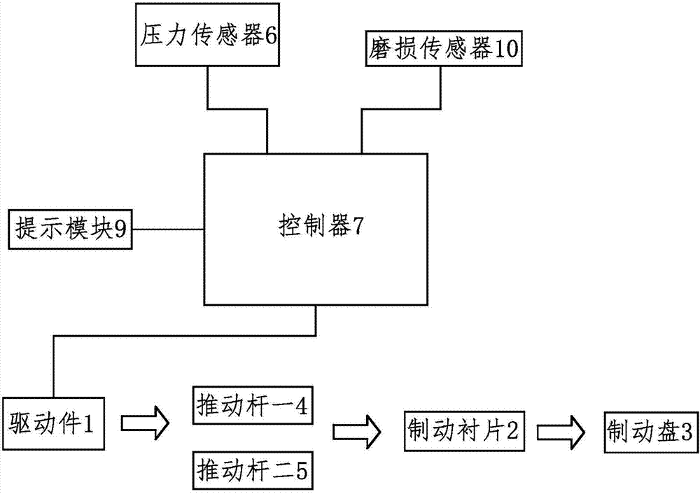
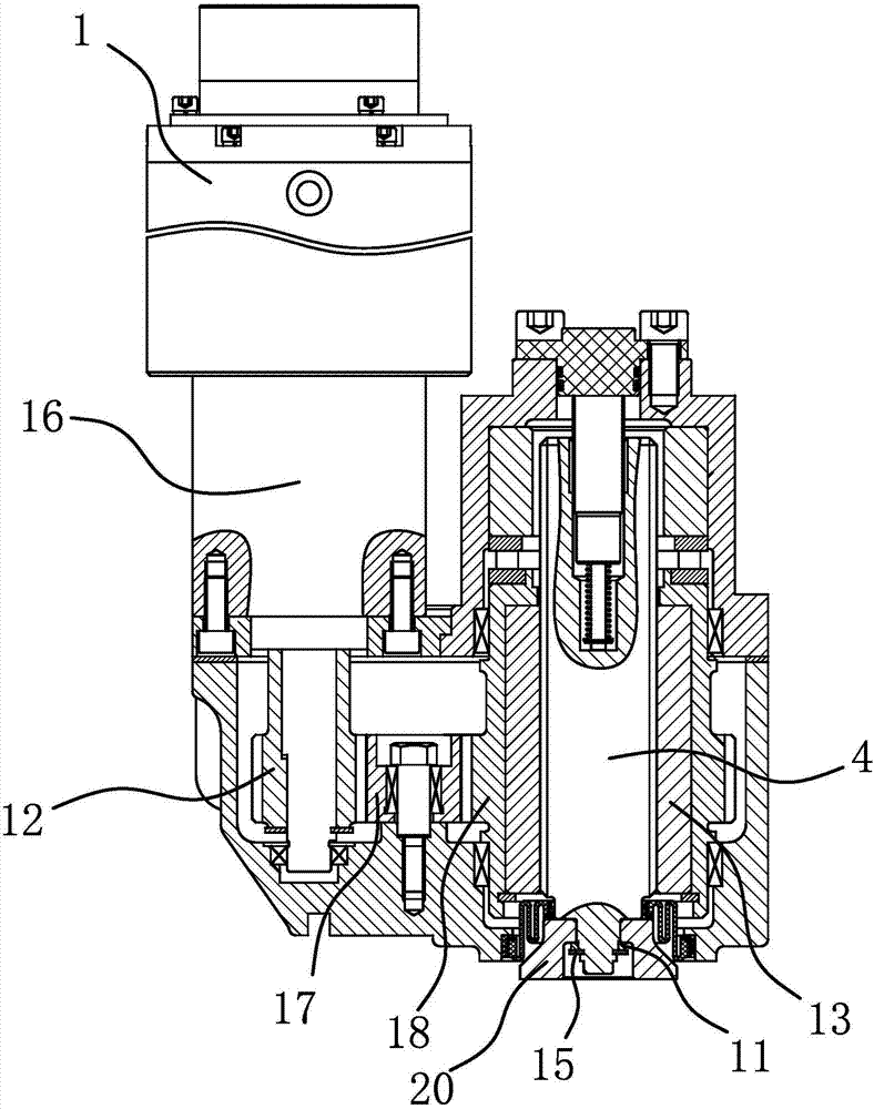
[0033] Such as figure 1 , image 3 , Figure 4 , Figure 5 and Figure 6 As shown, the electric brake includes a driver 1, a brake lining 2 and a brake disc 3, and a rod-shaped push rod one 4 and a push rod two 5 are arranged between the drive member 1 and the brake pad 2, One end of the first push rod 4 and one end of the second push rod 5 is connected to the driving member 1 through a synchronous transmission structure, and the other ends are fixedly connected to a long plate-shaped synchronous member 11 . Simultaneously, the outer sides of one end of the push rod one 4 and the push rod two 5 for connecting with the synchronous member 11 are respectively sleeved and axially fixed with ring-shaped push discs 20, and t...


PUM


Abstract

The invention provides an electric brake, which belongs to the technical field of vehicle braking. It solves the problem of poor braking effect of the existing electric brake. The electric brake includes a driving part, a brake lining, a brake disc, and a push rod 1 arranged between the driving part and the brake lining, and a pushing rod 2 is also arranged between the driving part and the brake lining. , the first push rod and the second push rod are in transmission connection with the above-mentioned driving member, and the first push rod and the second push rod can drive the brake lining against the above-mentioned brake disc under the drive of the drive member, and the electric brake also includes Two pressure sensors and a controller, the two pressure sensors can respectively detect the magnitude of the braking force exerted by the push rod 1 and the push rod 2 on the above-mentioned brake lining and send the braking force information to the above-mentioned controller, the The controller can receive the braking force information from the pressure sensor and control the driving force output by the driving member. The electric brake has the advantage of good braking effect.

Description

technical field [0001] The invention belongs to the technical field of vehicle braking and relates to an electric brake. Background technique [0002] The braking system is an important part of the car, and the braking devices of most existing cars are hydraulic brakes. When braking, the driver controls the hydraulic brake master cylinder through the pedal to pressurize through the vacuum booster, and transmits it to the brake cylinders of each wheel through hydraulic pipelines to perform hydraulic braking on the disc brakes. However, during the use of the hydraulic braking system, due to the use of hydraulic pipelines for braking force transmission, oil leakage is prone to occur and the response speed is slow. [0003] For this reason, people have designed a kind of electric brake and have applied for Chinese patent (its application number is: 200820226958.2; Its announcement number is: CN201326669Y), this electric brake comprises brake caliper, brake cylinder and brake cy...

Claims


Application Information

Patent Timeline
Patent Type & Authority Applications(China)
IPC IPC(8): F16D65/18F16D66/00F16D66/02F16D55/22F16D121/24F16D125/40
Inventor 肖水波罗少卿田鹏杨来科林聪付元念
Owner LONGZHONG HLDG GRP
Why Eureka
Try Eureka