Deceleration compensating method for vehicle, control system and vehicle

A compensation method and deceleration control technology, applied in vehicle parts, brakes, electric vehicles, etc., can solve problems such as changes, inability to stop and brake, traffic accidents, etc., to save power consumption, reduce accident rates, The effect of improving braking safety

Inactive Publication Date: 2018-02-13
FAFA AUTOMOBILE (CHINA) CO LTD
View PDF6 Cites 1 Cited by
  • Summary
  • Abstract
  • Description
  • Claims
  • Application Information

AI Technical Summary

Problems solved by technology

[0005] The purpose of the present invention is to provide a deceleration compensation method for vehicles, a control system and a vehicle to solve the problem in the prior art that after adding a wind power generator to the vehicle, the resistance provided by the wind power generator moves along with the vehicle. There will be changes during the braking process, which will bring a misjudgment to the driver, that is, the braking cannot be stopped within the expected braking deceleration distance, resulting in traffic accidents

Method used


Image

  • Deceleration compensating method for vehicle, control system and vehicle
  • Deceleration compensating method for vehicle, control system and vehicle
  • Deceleration compensating method for vehicle, control system and vehicle

Examples


Embodiment Construction

[0029] The specific implementation manners of the present invention will be further described in detail below in conjunction with the accompanying drawings and embodiments. The following examples are used to illustrate the present invention, but are not intended to limit the scope of the present invention.

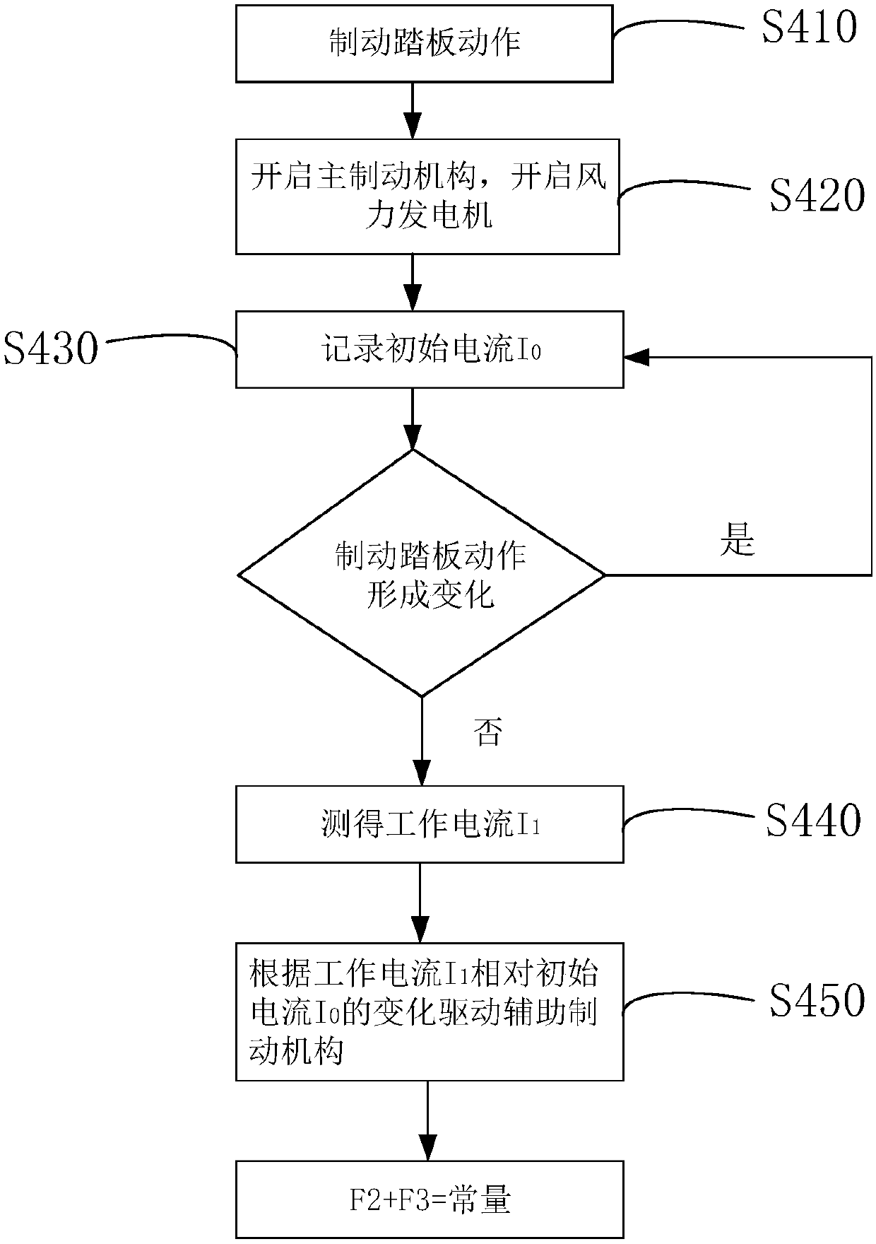
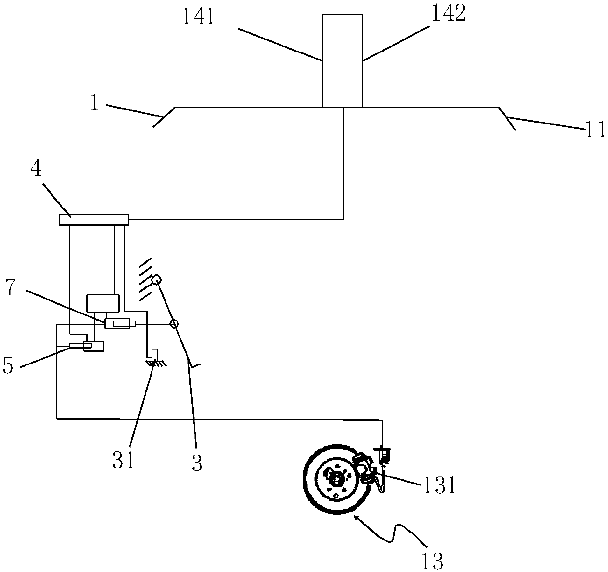
[0030] refer to figure 1 , figure 2 ,in figure 1 A deceleration compensation method for a vehicle in this embodiment is schematically shown. Wherein, the vehicle 1 can be a train, a passenger car or a freight car and the like. The method includes:

[0031] In step S410, when the brake pedal 3 is detected to be actuated, it means that the driver starts to step on the brake pedal 3 and the vehicle needs to be braked to decelerate. At this time, the process proceeds to step S420.

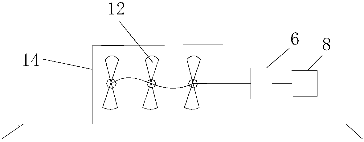
[0032] Step S420, as a response to the action of the brake pedal 3, drive the main brake mechanism 7 to generate the first braking force F that can be provided to the vehicle 1 for braking an...


PUM


Abstract

The invention discloses a deceleration compensating method for a vehicle, a control system and the vehicle. The method includes the steps of driving a main brake mechanism when detecting the movementof a brake pedal so as to provide first brake force F1 of brake deceleration for the vehicle, stating a wind driven generator installed on the vehicle so as to generate first auxiliary brake force F2for brake deceleration of the vehicle, recording the initial current I0 generated when the wind driven generator is started, measuring the work current I1 generated in the working process of the winddriven generator, and driving an auxiliary brake mechanism according to the change of the working current I1 relative to the initial current I0 to provide second auxiliary brake force F3 of brake deceleration for the vehicle so as to compensate for the change of the first auxiliary brake force F3. The method has the advantages of being high in brake safety and saving energy.

Description

technical field [0001] The invention relates to the field of vehicle braking, in particular to a deceleration compensation method for a vehicle, a control system and the vehicle. Background technique [0002] At present, the braking deceleration distance of the vehicle is relatively long, and the loss of the wheels is relatively serious. In addition, for large passenger cars or trucks, the braking deceleration distance is longer, which greatly increases the probability of traffic accidents. [0003] In the prior art, there is a wind turbine installed on the vehicle. The main purpose is to convert wind energy into electric energy to supplement the battery of the vehicle during deceleration. Objectively, the wind generator can also increase the braking resistance of the vehicle to reduce the braking force of the vehicle. Deceleration distance. However, this will produce a new problem, that is, compared with the original wind turbine, the driver can achieve vehicle braking wi...

Claims


Application Information

Patent Timeline
IPC IPC(8): B60T8/171H02J7/14
CPCH02J7/14B60T8/171B60T2201/03B60T2201/02
Inventor 杨连松栾云飞
Owner FAFA AUTOMOBILE (CHINA) CO LTD
Why Eureka
Try Eureka