
Spherical intelligent aggregate for monitoring of health of concrete structure

A concrete structure and intelligent aggregate technology, which is applied in the use of acoustic wave emission technology for material analysis, the use of sound waves/ultrasonic waves/infrasonic waves for material analysis, and measurement devices, can solve the problem of reducing monitoring sensitivity and accuracy, sensors affecting monitoring effects, and engineering Troublesome personnel and other problems, to achieve the effect of full-angle detection, fast and accurate health status evaluation, and high reliability of information

Inactive Publication Date: 2017-12-29
来安中衡物联网设备科技有限公司
View PDF2 Cites 4 Cited by
  • Summary
  • Abstract
  • Description
  • Claims
  • Application Information

AI Technical Summary

Problems solved by technology

This method can monitor and warn of abnormal conditions such as sound, vibration, stress change, and cracks of buildings in the monitoring area. Narrow” problem, and the sensors installed on the surface of the building are easily affected by the external environment, which affects its monitoring effect
[0004] Furthermore, most of the sensors currently used for health conditions such as concrete structure crack detection are piezoelectric sensors based on the piezoelectric effect, but traditional piezoelectric sensors use pure ceramic materials such as PZT as transducer elements, and their acoustic impedance, elastic modulus The material parameters such as volume are quite different from the concrete material, so a large amount of acoustic signals are reflected at the interface between the concrete and the sensor, which reduces the sensitivity and accuracy of monitoring

Method used


Image

  • Spherical intelligent aggregate for monitoring of health of concrete structure
  • Spherical intelligent aggregate for monitoring of health of concrete structure
  • Spherical intelligent aggregate for monitoring of health of concrete structure

Examples


Embodiment Construction

[0023] The present invention provides a spherical intelligent aggregate used for concrete structure health monitoring. In order to make the purpose, technical solution and effect of the present invention clearer and clearer, the present invention will be further described in detail below. It should be understood that the specific embodiments described here are only used to explain the present invention, not to limit the present invention.

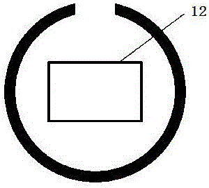
[0024] A spherical intelligent aggregate for health monitoring of concrete structures, which includes hollow spherical composite material particles 10 (such as figure 1 shown), the negative electrode 13 formed on the inner surface of the hollow spherical composite particle 10 and the positive electrode 14 on the outer surface (such as image 3 shown), the encapsulation structure that is encapsulated outside the hollow spherical composite material particle 10 and provided with an electromagnetic shielding layer 30 (combined with Figure 4 a...


PUM


Abstract

The invention discloses a spherical intelligent aggregate for health monitoring of concrete structures, which comprises hollow spherical composite material particles, a negative electrode formed on the inner surface of the hollow spherical composite material particle and a positive electrode on the outer surface, and is encapsulated in the hollow An encapsulation structure with an electromagnetic shielding layer outside the spherical composite material particles, and cables and wireless transceivers connected to the positive electrode, negative electrode, and electromagnetic shielding layer; the spherical smart aggregate is formed in an array during the concrete construction stage Pre-embedded in the concrete structure under test, collect the acoustic signal detected by the spherical intelligent aggregate in wired or wireless working mode, and send it to the remote terminal system. The remote terminal system analyzes and records the received acoustic signal in real time to determine the concrete structure. overall health status. The invention can be embedded in the concrete during the construction of the building structure to realize long-term health monitoring of the concrete structure.

Description

technical field [0001] The invention relates to the field of concrete structures, in particular to a spherical intelligent aggregate used for health monitoring of concrete structures. Background technique [0002] At present, most of the sensors used for health monitoring of concrete structures are sensors that require a special process to be installed inside the concrete structure. This process often requires that the corresponding sensors be installed at the same time when the structure is built, so it needs to be planned in advance. At the same time, because the design of these sensors is mostly disc or ring, the monitoring range has obvious directionality. Usually, in the area that deviates from the detection direction of the sensor at a certain angle, the monitoring sensitivity of the sensor will decrease significantly, so its detection "field of view is narrow". [0003] The domestic invention patent application with the application number 201010607717.4 discloses a se...

Claims


Application Information

Patent Timeline
IPC IPC(8): G01N29/14G01N29/24
CPCG01N29/14G01N29/245G01N2291/0232G01N2291/2698
Inventor 李宗津陆有源张津瑞
Owner 来安中衡物联网设备科技有限公司
Learn More