
Zero-clearance rolling system and method based on PLC (Programmable Logic Controller) control

A technology without gaps and control cabinets, applied in metal rolling, metal rolling, rolling mill control devices, etc., can solve the problems of unstable negative difference, stacking, reducing output, etc., to reduce fluctuations in diameter changes and improve yield The effect of improving the yield and yield

Inactive Publication Date: 2017-12-29
天津天合共创科技有限公司
View PDF0 Cites 7 Cited by
  • Summary
  • Abstract
  • Description
  • Claims
  • Application Information

AI Technical Summary

Problems solved by technology

[0003] (1) The segments of the 1# flying shear in the rough rolling unit are not clear; because the distance between the billets is too close, it will cause the 1# flying shear (the main function of the flying shear: the rolled piece in the transverse shearing movement, cutting head, cutting Tail, fixed length) cannot distinguish the head or tail of the billet, and cannot perform head and tail cutting operations, which will lead to unqualified finished products
[0004] (2) It will cause the rolled piece to penetrate into the looper, and process accidents such as rear-end collision and stacking of steel will occur: because the steel billets enter the rolling mill end-to-end, it will cause every two steel billets to be too close in the rolling mill. If it is not completed, the next steel billet will follow, drill sleeves will occur, and process accidents will occur. If they occur frequently, the operation rate will be greatly reduced and the output will be reduced.
[0005] (3) If the traditional process is in the rolling process, if the steel billet enters the rolling mill end to end, in order to prevent the 1# flying shear from being unable to identify the head and tail of the rolled piece; to prevent the occurrence of drilling into the looper, the commonly used method is Steel drawing and rolling, drawing and rolling will lead to unguaranteed material shape and product quality, unstable negative difference, and high accident rate

Method used


Image

  • Zero-clearance rolling system and method based on PLC (Programmable Logic Controller) control

Examples


Embodiment Construction

[0037] The technical solutions of the present invention will be clearly and completely described below in conjunction with the accompanying drawings. Apparently, the described embodiments are some of the embodiments of the present invention, but not all of them. Based on the embodiments of the present invention, all other embodiments obtained by persons of ordinary skill in the art without making creative efforts belong to the protection scope of the present invention.

[0038] In the description of the present invention, it should be noted that the terms "center", "upper", "lower", "left", "right", "vertical", "horizontal", "inner", "outer" etc. The indicated orientation or positional relationship is based on the orientation or positional relationship shown in the drawings, and is only for the convenience of describing the present invention and simplifying the description, rather than indicating or implying that the referred device or element must have a specific orientation, ...


PUM


Abstract

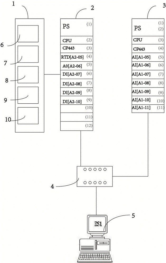
The present invention proposes a non-gap rolling system and method based on PLC control, including an original rolling line control cabinet, a switch, a non-gap control cabinet, and a rolling production line. The rolling production line is connected to the original rolling line control cabinet. The rolling line control cabinet is connected to the switch, and the output ends of the switch are respectively connected to the operation station and the gapless control cabinet, wherein the rolling production line includes a rough rolling unit, a flying shear unit, an intermediate rolling unit, a looper unit, and a finishing rolling unit , the rough rolling unit, the flying shear unit, the intermediate rolling unit, the looper unit, and the finishing rolling unit are connected in sequence, and each includes a multi-stand rolling mill. The present invention controls the different gathering speeds of two continuous steel slabs by establishing a two-stage gathering relationship to realize seamless steel feeding.

Description

technical field [0001] The invention relates to the technical field of rolling control systems, in particular to a gapless rolling system and method based on PLC control, which are applied to continuous rolling production lines of bars, angle steels, and wires. Background technique [0002] A hot-rolled steel production line generally includes a rough rolling unit, an intermediate rolling unit, and a finishing rolling unit. In the traditional production process, when two continuous billets enter the first rolling mill of the rough rolling unit, a minimum time interval of 2 seconds must be maintained to ensure smooth production. conduct. Under the control of traditional technology, the time interval of 2S is canceled for two consecutive billets, and the steel feeding without gaps will lead to the following process accidents: [0003] (1) The segments of the 1# flying shear in the rough rolling unit are not clear; because the distance between the billets is too close, it will...

Claims


Application Information

Patent Timeline
IPC IPC(8): B21B37/00B21B37/50
CPCB21B37/00B21B37/005B21B37/50B21B2201/06B21B2273/02B21B2273/20B21B2275/10B21B2275/12
Inventor 李振龙
Owner 天津天合共创科技有限公司
Learn More