
Energy-saving and compact type guide rail clamping device

A clamper, compact technology, applied in the direction of brake parts, brake parts, brake types, etc., can solve the problems of small effective space, poor machining accuracy, etc., achieve wide application range, large braking force, and avoid guide rail scratches The effect of injury

Pending Publication Date: 2017-12-26
济南申健化工科技有限公司
View PDF4 Cites 9 Cited by
  • Summary
  • Abstract
  • Description
  • Claims
  • Application Information

AI Technical Summary

Problems solved by technology

[0003] The invention provides an energy-saving and compact guide rail clamper to solve the problems of poor machining accuracy and small effective space in existing machining centers

Method used


Image

  • Energy-saving and compact type guide rail clamping device
  • Energy-saving and compact type guide rail clamping device
  • Energy-saving and compact type guide rail clamping device

Examples


example 1

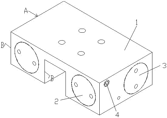
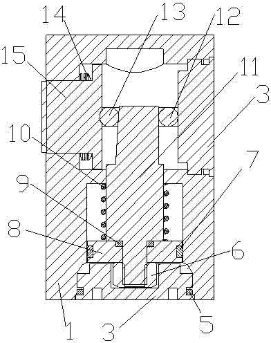
[0030] Such as figure 1 , figure 2 , image 3 , Figure 4 , Figure 5 , Figure 6 , Figure 7 , Figure 8 , Figure 9 and Figure 10As shown, a normally open guide rail clamp has a symmetrical main structure with left and right ends, and each end is composed of a clamp body 1, a cylinder cover 2, a clamp support block 3, a sealing screw 4, and a cylinder cover sealing ring 5 , cylinder rod fixing nut 6, piston sealing ring 7, piston 8, cylinder rod sealing ring 9, compression spring 10, cylinder rod 11, clamping A guide post 12, clamping B guide post 13, spring washer 14 and clamping block 15, The spring washer 14 is a wave spring washer or a butterfly spring washer. The clamp body 1 is set to fasten the fixed thread 1-1 on the line rail and the air outlet hole 1-3 of the cylinder, and the air inlet threaded hole 1 of the clamp body 1 -2 communicates with the air inlet 1-4 and is used to connect the air inlet joint and the sealing screw 4, the air inlet 1-4 is arrang...

example 2

[0035] Such as Figure 8 , Figure 9 , Figure 10 , Figure 11 , Figure 12 , Figure 13 , Figure 14 , Figure 15 and Figure 16 As shown, a normally closed guide rail clamp has a symmetrical main structure with left and right ends, and each end is composed of a clamp body 1, a cylinder cover 2, a clamp support block 3, a sealing screw 4, and a cylinder cover sealing ring 5 , cylinder rod fixing nut 6, piston sealing ring 7, piston 8, cylinder rod sealing ring 9, compression spring 10, cylinder rod 11, clamping A guide post 12, clamping B guide post 13, spring washer 14 and clamping block 15, The spring washer 14 is a wave spring washer or a butterfly spring washer. The clamp body 1 is set to fasten the fixed thread 1-1 on the line rail and the air outlet hole 1-3 of the cylinder, and the air inlet threaded hole 1 of the clamp body 1 -2 communicates with the air inlet 1-4 and is used to connect the air inlet joint and the sealing screw 4, the air inlet 1-4 is arranged...


PUM


Abstract

The invention relates to an energy-saving and compact type guide rail clamping device. The energy-saving and compact type guide rail clamping device is provided with a body structure with symmetrical left and right ends, and each end is provided with a clamping device body, an air cylinder sealing cover, a clamping supporting block, a sealing screw, an air cylinder sealing cover sealing ring, an air cylinder rod fixing nut, a piston sealing ring, a piston, an air cylinder rod sealing ring, a compression spring, an air cylinder rod, a clamping guide column A, a clamping guide column B, a spring washer and a clamping block. The energy-saving and compact type guide rail clamping device is compact in structure, easy to install, wide in application scope and comprehensively suitable for various flat square rails and round guide rails on the market, double-side output pressure braking or simultaneous loosening is achieved, scratching of the guide rails is avoided to a certain degree, the output clamping brake force is large, the brake force as high as 2250 N can be output by a minimum-specification normally-opened type clamping device under the air pressure being 0.4 Mp, energy conservation and environmental protection are achieved, the gas consumption of compression gas is only 0.004 L during braking or loosening motion each time.

Description

technical field [0001] The invention relates to the technical field of profile processing equipment, in particular to an energy-saving and compact guide rail clamp. Background technique [0002] The existing guide rail clamps on the market generally increase the braking force by using a simple lever principle or a structure in which the spiral motion is converted into a linear motion. Because the cylinder bore is large, the overall volume or installation takes up The space is large, the amount of compressed gas is also large, and it is generally suitable for circular guide rails but not for flat rails, that is, square guide rails, which limits the scope of application to a certain extent. Contents of the invention [0003] The invention provides an energy-saving and compact guide rail clamper to solve the problems of poor machining accuracy and small effective space in existing machining centers. [0004] The technical solution adopted by the present invention to solve it...

Claims


Application Information

Patent Timeline
IPC IPC(8): F16D63/00F16D65/14F16D65/04F16D121/04F16D125/02F16D125/08F16D125/66
CPCF16D63/00F16D65/0037F16D65/04F16D65/14F16D2125/08F16D2125/02F16D2125/66F16D2121/04
Inventor 韩帅吕路平
Owner 济南申健化工科技有限公司
Learn More