


Quick Research
Generate reliable direction feasibility study reports for your R&D in just a few steps.

Technical Q&A
Discover and master advanced knowledge NOW. Basics, ideas, possibilities, all at once.

Find Solutions
As an expert in R&D theories, this can generate solutions to your technical problems instantly.

Evaluate Feasibility
Analyze your overall solution with one click, know your potential R&D risks in advance.

Monitor Landscape
Get weekly tech updates, stay abreast of the latest tech innovations and key insights.
Sphygmomanometer
A sphygmomanometer and cuff technology, applied in the field of sphygmomanometers, can solve the problems of low measurement accuracy, inconvenient data reading, cumbersome operation, etc., and achieve the effects of reasonable layout design, not easy to be worn out, and simplified blood pressure measurement operations
- Summary
- Abstract
- Description
- Claims
- Application Information
AI Technical Summary
Problems solved by technology
Method used
Image

Examples
Embodiment 1
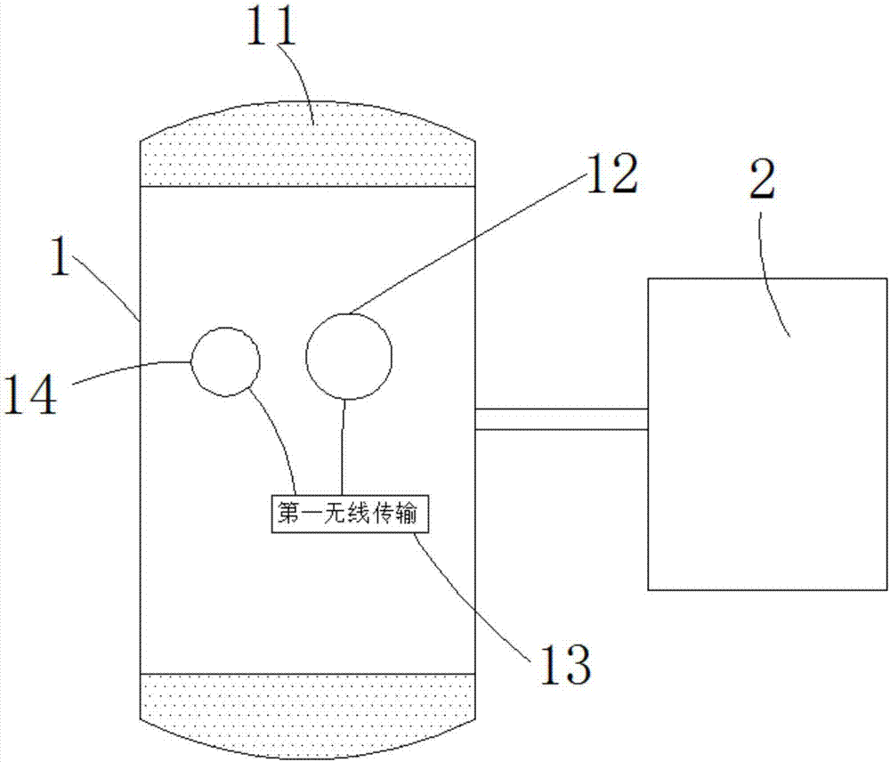
[0034] Such as Figure 1 to Figure 4 As shown, the present invention provides a blood pressure monitor, comprising: a cuff 1 and a controller 2 connected to the cuff 1;
[0035] An inflatable cavity is formed in the cuff 1, a pressure sensor 12 and a first wireless transmission module 13 electrically connected to the pressure sensor 12 are arranged in the cuff 1;
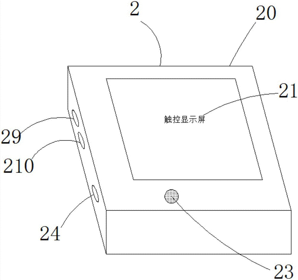
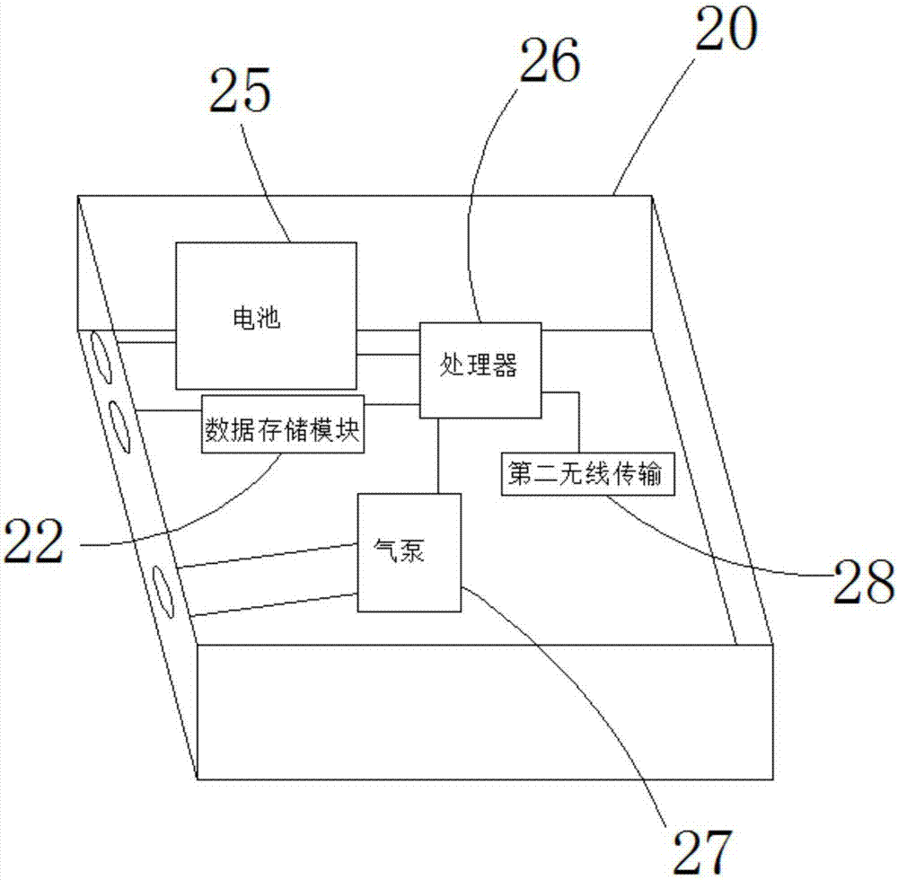
[0036] The controller 2 includes: a housing 20, a touch display screen 21 located on the outer surface of the housing 20, a speaker 23, an air delivery port 24, a charging socket 29 and a data transmission socket 210, and a A battery 25, a processor 26, an air pump 27, a second wireless transmission module 28 and a data storage module 22 in the casing 21;
[0037] The touch display screen 21, speaker 23, battery 25, air pump 27, second wireless transmission module 28, and data storage module 22 are all electrically connected to the processor 26, and the battery 25 is connected to the charging socket 29 Electricall...
Embodiment 2
[0044] A manufacturing process of a cuff of a sphygmomanometer, the steps are as follows:
[0045] ①, structure and molding
[0046] The inside of the cuff is provided with an inflatable cavity, and the two ends are provided with connecting buckles; the cuff is provided with a pulse sensor, a pressure sensor, and a first wireless transmission module electrically connected to the two;
[0047] The cuff is made of nylon, made of textile stitching, with a rubber inflatable cavity inside;
[0048] The connecting buckle is made of Velcro material;
[0049] ②, cuff wear-resistant layer spraying
[0050] Spray a wear-resistant layer on the surface of the cuff, and dry it at 55°C after spraying;
[0051] The wear-resistant layer is made of 30 parts of polyurethane acrylate, 4 parts of additives, 10 parts of polyorganosiloxane, 5 parts of solvent, 6.5 parts of imidazoquinolinic acid and 2.5 parts of tetrahydropalmatine in a reaction kettle at 65 ° C. 10 hours to make;
[0052] ③, ...
PUM
 Abstract
Description
Claims
Application Information
 - R&D Engineer
- R&D Manager
- IP Professional
- Industry Leading Data Capabilities
- Powerful AI technology
- Patent DNA Extraction
Browse by: Latest US Patents, China's latest patents, Technical Efficacy Thesaurus, Application Domain, Technology Topic, Popular Technical Reports.
© 2024 PatSnap. All rights reserved.Legal|Privacy policy|Modern Slavery Act Transparency Statement|Sitemap|About US| Contact US: help@patsnap.com