Multifunctional jig for key and connector detection in smart phone
A smart phone and connector technology, applied in electrical connection testing, instruments, measuring electricity, etc., can solve the problems of unstable force applied on the surface of the product, affecting the reliability of product testing, limited adjustable range, etc., to achieve savings The time of detection, the effect of improving the accuracy and overall component utilization of the equipment, improving the accuracy and sensitivity
- Summary
- Abstract
- Description
- Claims
- Application Information
AI Technical Summary
Problems solved by technology
Method used
Image
Examples
Embodiment 1
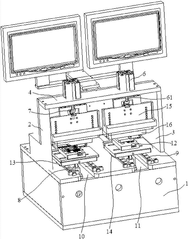
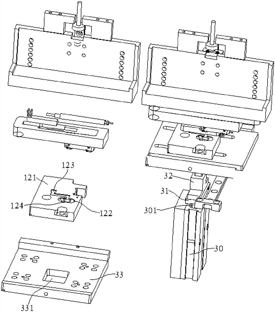
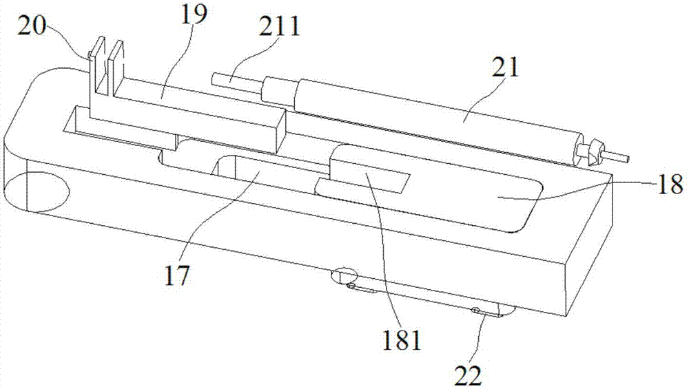
[0029] Embodiment 1: A multifunctional jig for detecting buttons and connectors in a smart phone, comprising a box body 1, a left support board 2, a right support board 3 and a beam 4, the left support board 2, the right support board 3 is fixed on both sides of the box body 1, and the two ends of the crossbeam 4 are fixed on the upper ends of the left support plate 2 and the right support plate 3 respectively, and two upper vertical cylinders 6 are installed on the upper surface of the crossbeam 4. The piston rod 61 of the cylinder 6 passes through the through hole of the beam 4, and the end of the piston rod 61 is equipped with a disc 7 positioned at the bottom of the beam 4;
[0030] Two first guide rails 8 and two second guide rails 9 are installed in parallel on the upper surface of the box body 1. There is a first hollow groove 10 between the two first guide rails 8 on the left side, and a first hollow groove 10 between the two first guide rails 8 on the right side. Ther...
Embodiment 2
[0039] Embodiment 2: A multifunctional jig for detecting buttons and connectors in smart phones, including a box body 1, a left support board 2, a right support board 3 and a beam 4, the left support board 2, the right support board 3 is fixed on both sides of the box body 1, and the two ends of the crossbeam 4 are fixed on the upper ends of the left support plate 2 and the right support plate 3 respectively, and two upper vertical cylinders 6 are installed on the upper surface of the crossbeam 4. The piston rod 61 of the cylinder 6 passes through the through hole of the beam 4, and the end of the piston rod 61 is equipped with a disc 7 positioned below the beam 4;
[0040] Two first guide rails 8 and two second guide rails 9 are installed in parallel on the upper surface of the box body 1. There is a first hollow groove 10 between the two first guide rails 8 on the left side, and a first hollow groove 10 between the two first guide rails 8 on the right side. There is a second...
PUM
 Abstract
Description
Claims
Application Information
 - R&D Engineer
- R&D Manager
- IP Professional
- Industry Leading Data Capabilities
- Powerful AI technology
- Patent DNA Extraction
Browse by: Latest US Patents, China's latest patents, Technical Efficacy Thesaurus, Application Domain, Technology Topic, Popular Technical Reports.
© 2024 PatSnap. All rights reserved.Legal|Privacy policy|Modern Slavery Act Transparency Statement|Sitemap|About US| Contact US: help@patsnap.com


