Polarized rotation retrodirective array

A technology of direction backtracking and polarization rotation, which is applied to the combination of antenna elements with different polarization directions, the structural form of radiation elements, and the structural connection of antenna grounding switches, etc., which can solve problems such as practical limitations, inapplicability, and complex feeding systems , to achieve the effect of avoiding loss and compact structure

Active Publication Date: 2017-12-22
UNIV OF ELECTRONICS SCI & TECH OF CHINA
View PDF3 Cites 4 Cited by
  • Summary
  • Abstract
  • Description
  • Claims
  • Application Information

AI Technical Summary

Problems solved by technology

Luxey C et al. disclose a retrodirective transponder with polarization duplexing for dedicated short-range communications [J]. IEEE Transactions on Microwave Theory & Techniques , 2014,47(9):1910-1915.); However, due to the use of dual-line polarization, the array needs accurate alignment of the transmitting and receiving antennas to avoid polarization loss and is not suitable for communication with moving targets
Choi JH et al. designed a retrodirective array that emits orthogonally polarized waves for incident waves of any polarization (Choi J H, Dong Y, Sun J S, et al. Retrodirective Array Immune to Incident Waves With Arbitrary Polarizations[J ].IEEE Transactions on Antennas&Propagation, 2013,61(12):6008-6013.), this array can reduce the polarization mismatch loss without accurate alignment of the transmitting and receiving antennas; Requires four mixers, four amplifiers, and two phase delay lines, limiting its practicality

Method used


Image

  • Polarized rotation retrodirective array
  • Polarized rotation retrodirective array
  • Polarized rotation retrodirective array

Examples


Embodiment Construction

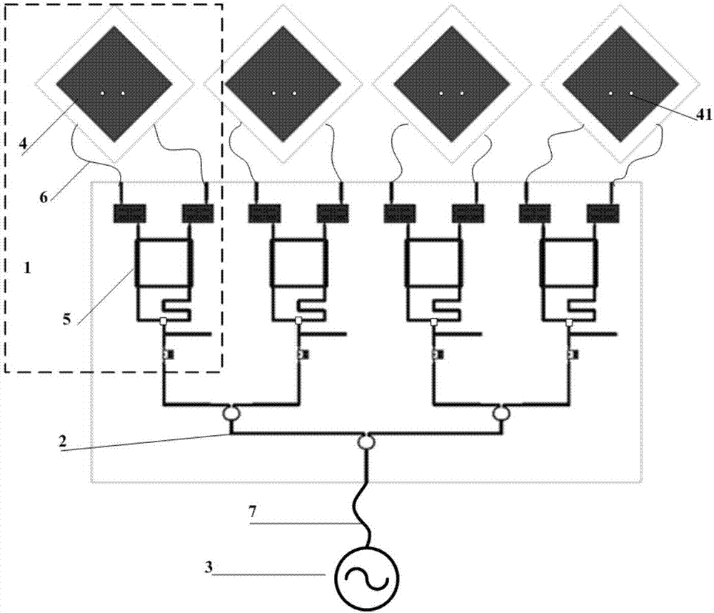
[0016] The present invention will be further described below in conjunction with accompanying drawing and specific embodiment: figure 1 As shown, a polarization rotation direction traceback array includes M polarization rotation direction traceback subunits 1, M power dividers 2, and local oscillator sources 3; the M is an integer greater than or equal to 3; the The polarization rotation direction backtracking subunit is composed of a doubly-fed dual-polarized patch antenna and a phase conjugate mixer; the doubly-fed patch antenna and the phase conjugate mixer pass through two equal-length first radio frequency cables Connected together; the phase conjugate mixer and the M-way power divider are prepared on the same dielectric substrate, and the F4B plate with a thickness of 0.508mm is used here; the local oscillator source is connected through the second radio frequency cable to the input port of the M-way power splitter. The phase conjugate mixer 5 is printed on the dielectr...


PUM


Abstract

The invention discloses a polarized rotation retrodirective array which is composed of a doubly fed square patch, a phase-conjugating mixer and a local oscillator power divider. The polarized rotation retrodirective array can be used in the microwave millimeter wave communication system, radio frequency identification and wireless energy transmission. The advantage is that the polarized rotation retrodirective array can realize backtrace of the orthogonally polarized wave of the wave in any direction, the phase-conjugating circuit is simple in structure, the local oscillation suppression is high, the cost is low and the processing cycle is short.

Description

technical field [0001] The invention belongs to the field of microwave and millimeter wave systems, in particular to a direction backtracking array in the microwave and millimeter wave system. Background technique [0002] The direction backtracking array can automatically forward a signal pointing to the direction of the incoming wave without knowing the direction of the incoming wave. Because it has the characteristic of automatically tracking the incoming wave direction without complex signal processing equipment, it has a great application prospect in the fields of wireless communication, wireless energy transmission, radio frequency transmission and so on. [0003] Existing directional traceback arrays generally transmit and receive at the same frequency, so orthogonal polarization is often used for transceiver isolation. Luxey C et al. disclose a retrodirective transponder with polarization duplexing for dedicated short-range communications [J]. IEEE Transactions on M...

Claims


Application Information

Patent Timeline
Patent Type & Authority Applications(China)
IPC IPC(8): H01Q1/38H01Q1/50H01Q21/24
CPCH01Q1/38H01Q1/50H01Q21/24
Inventor 林先其杨永穆曾姜杰许冬冬黄登祥贾小翠朱忠博樊勇
Owner UNIV OF ELECTRONICS SCI & TECH OF CHINA
Why Eureka
Try Eureka