
A kind of array substrate and its manufacturing method

A technology of an array substrate and a manufacturing method, which is applied in the field of display, can solve the problems affecting the conductorization effect of the semiconductor layer, and the semiconductor layer cannot achieve the expected effect, and achieve the effect of improving the display effect, reducing the defect state, and ensuring stability

Active Publication Date: 2020-09-15
HKC CORP LTD
View PDF5 Cites 0 Cited by
  • Summary
  • Abstract
  • Description
  • Claims
  • Application Information

AI Technical Summary

Problems solved by technology

[0004] In the top-gate self-aligned thin film transistor manufacturing process, the semiconductor layer needs to be conductorized. However, the semiconductor layer that has undergone the conductorization process will be significantly affected in the subsequent manufacturing process, affecting the conductorization effect of the semiconductor layer. Semiconducting layer does not work as expected

Method used


Image

  • A kind of array substrate and its manufacturing method
  • A kind of array substrate and its manufacturing method
  • A kind of array substrate and its manufacturing method

Examples


Embodiment Construction

[0057] Specific structural and functional details disclosed herein are representative only and for purposes of describing example embodiments of the present invention. This invention may, however, be embodied in many alternative forms and should not be construed as limited to only the embodiments set forth herein.

[0058] In describing the present invention, it is to be understood that the terms "central", "lateral", "upper", "lower", "left", "right", "vertical", "horizontal", "top", The orientation or positional relationship indicated by "bottom", "inner", "outer", etc. is based on the orientation or positional relationship shown in the drawings, and is only for the convenience of describing the present invention and simplifying the description, rather than indicating or implying the referred device Or elements must have a certain orientation, be constructed and operate in a certain orientation, and thus should not be construed as limiting the invention. In addition, the te...


PUM


Abstract

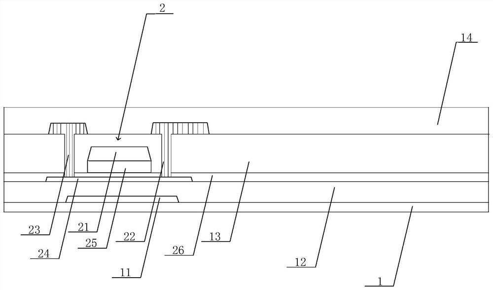
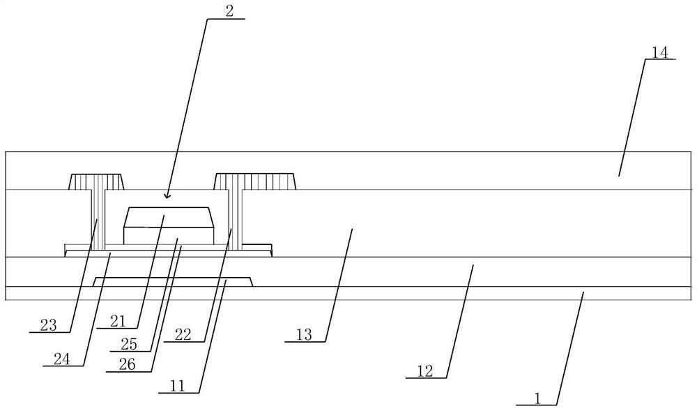
The invention discloses an array substrate, and the array substrate comprises: a substrate; a light-shielding layer formed on the substrate; a buffer layer formed on the light-shielding layer; a semiconductor layer formed on the buffer layer; a protective layer , formed on the semiconductor layer; an insulating layer, formed on the protective layer; an interlayer dielectric layer, formed on the protective layer; a source layer, a drain layer and a gate are also arranged on the substrate layer, the source layer and the drain layer are formed on the interlayer dielectric layer, and the source layer and the drain layer are respectively connected to conductorized parts at both ends of the semiconductor layer, the An insulating layer is arranged between the gate layer and the semiconductor layer, the interlayer dielectric layer covers the gate and the protective layer, and the insulating layer is covered on the semiconductor layer to effectively ensure that the required conductorization The region of the semiconductor layer will not be exposed, which can effectively reduce the impact on the impedance of the conductorized part of the semiconductor layer during the subsequent process.

Description

technical field [0001] The present invention relates to the field of display technology, in particular to an array substrate and a manufacturing method thereof. Background technique [0002] The display has many advantages such as thin body, power saving, no radiation, etc., and has been widely used. Most of the displays currently on the market are backlight displays, which include a display panel and a backlight module. The working principle of the display panel is to place liquid crystal molecules between two parallel substrates, and apply a driving voltage on the two substrates to control the rotation direction of the liquid crystal molecules, so as to refract light from the backlight module to generate images. [0003] Among them, Thin Film Transistor-Liquid Crystal Display (TFT-LCD) has gradually occupied a dominant position in the display field due to its low power consumption, excellent picture quality, and high production yield. Similarly, a thin film transistor di...

Claims


Application Information

Patent Timeline
Patent Type & Authority Patents(China)
IPC IPC(8): H01L27/12H01L21/77
CPCH01L27/1214H01L27/127G02F1/136209H01L29/78633H01L29/7869H01L27/1248G02F1/136227H01L27/14612
Inventor 何怀亮
Owner HKC CORP LTD
Learn More