
Microwave signal frequency-hopping time measurement circuit

A technology for measuring circuit and frequency hopping time, which is used in electrical unknown time interval measurement, devices for measuring time interval, clocks and other directions, and can solve problems such as narrow real-time processing bandwidth.

Pending Publication Date: 2017-12-22
ANHUI SUN CREATE ELECTRONICS
View PDF8 Cites 4 Cited by
  • Summary
  • Abstract
  • Description
  • Claims
  • Application Information

AI Technical Summary

Problems solved by technology

In practical applications, the measurement device based on the high-speed FFT processing method of down-conversion has the disadvantage of narrow real-time processing bandwidth, and the measurement device of the frequency fast synchronization tracking processing method has the limitation that the frequency hopping frequency must be known in advance, and an external synchronization signal is required

Method used


Image

  • Microwave signal frequency-hopping time measurement circuit
  • Microwave signal frequency-hopping time measurement circuit
  • Microwave signal frequency-hopping time measurement circuit

Examples


Embodiment Construction

[0019] The following will clearly and completely describe the technical solutions in the embodiments of the present invention with reference to the accompanying drawings in the embodiments of the present invention. Obviously, the described embodiments are only some, not all, embodiments of the present invention. Based on the embodiments of the present invention, all other embodiments obtained by persons of ordinary skill in the art without making creative efforts belong to the protection scope of the present invention.

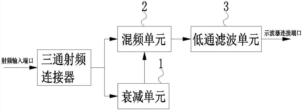
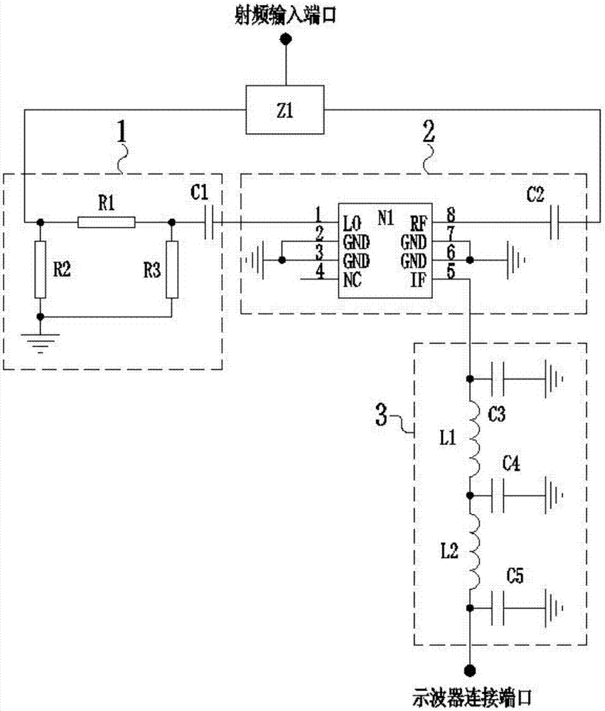
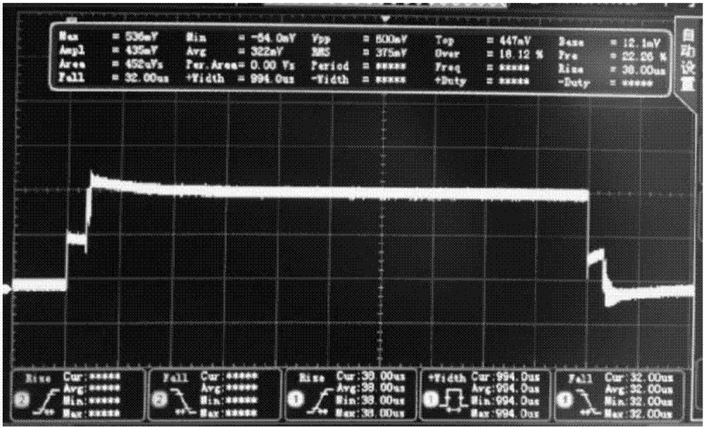
[0020] Such as figure 1 As shown, a microwave signal frequency hopping time measurement circuit includes an attenuation unit 1, a frequency mixing unit 2, and a low-pass filter unit 3; the input terminals of the voltage-controlled oscillation unit 1 and the frequency mixing unit 2 are all of the measurement circuit The input port, the output end of the voltage-controlled oscillation unit 1 is connected to the input end of the frequency mixing unit 2, the outpu...


PUM


Abstract

The invention belongs to the technical field of microwave signal testing, and particularly relates to a microwave signal frequency-hopping time measurement circuit. The frequency-hopping time measurement circuit comprises an attenuation unit, a frequency mixing unit and a lowpass filtering unit; the input ends of a voltage-controlled oscillation unit and the frequency mixing unit are both input ports of the measurement circuit, the output end of the voltage-controlled oscillation unit is connected with the input end of the frequency mixing unit, the output end of the frequency mixing unit is connected with the input end of the lowpass filtering unit, and the output end of the lowpass filtering unit is an output port of the measurement circuit. The microwave signal frequency-hopping time measurement circuit can effectively measure the frequency hopping time in a wide frequency range, and measurement can be conducted without additionally adding synchronizing signals or knowing the modulation frequency in advance.

Description

technical field [0001] The invention belongs to the technical field of microwave signal testing, and in particular relates to a microwave signal frequency hopping time measurement circuit. Background technique [0002] Fast, simple, low-cost, effective, true and reliable microwave signal frequency hopping time measurement device has a wide range of needs in equipment development, product testing, and index verification in the fields of radar, countermeasures, communications, and test instruments. [0003] There are many traditional microwave signal frequency hopping time measurement devices, such as the measurement device based on the high-speed FFT processing method of down-conversion, and the measurement device of the frequency fast synchronous tracking processing method. In practical applications, the measurement device based on the high-speed FFT processing method of down-conversion has the disadvantage of narrow real-time processing bandwidth, and the measurement device...

Claims


Application Information

Patent Timeline
Patent Type & Authority Applications(China)
IPC IPC(8): G04F10/00
CPCG04F10/00
Inventor 鲁长来毛飞汪炜谢迟
Owner ANHUI SUN CREATE ELECTRONICS
Learn More