
A container crane for U-shaped berth

A container crane and container technology, which is applied in the direction of cranes, cranes, and traveling mechanisms of trolleys, can solve the problems of restricted area switching, low transportation efficiency, and large investment.

Active Publication Date: 2019-11-15
王燏斌
View PDF11 Cites 0 Cited by
  • Summary
  • Abstract
  • Description
  • Claims
  • Application Information

AI Technical Summary

Problems solved by technology

[0002] The existing container transportation mainly includes chassis vehicle system, straddle carrier system, gantry crane system and hybrid system; 1) chassis vehicle system: the demand for chassis vehicles is large, and the investment is large. The phenomenon of intermittent operation; it is not easy to realize automation; 2) Straddle carrier system: the front of the terminal adopts the container loading and unloading bridge on the shore to undertake the loading and unloading operations of ships, and the straddle carrier undertakes the horizontal transportation between the front of the terminal and the storage yard, as well as the storage of the storage yard. The loading and unloading operations of yards and vehicles entering and leaving the site; the switching of operating areas for straddle carriers is limited, and the conveying efficiency is not high

Method used


Image

  • A container crane for U-shaped berth
  • A container crane for U-shaped berth
  • A container crane for U-shaped berth

Examples


Embodiment Construction

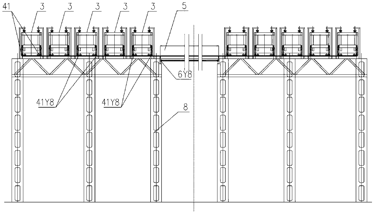
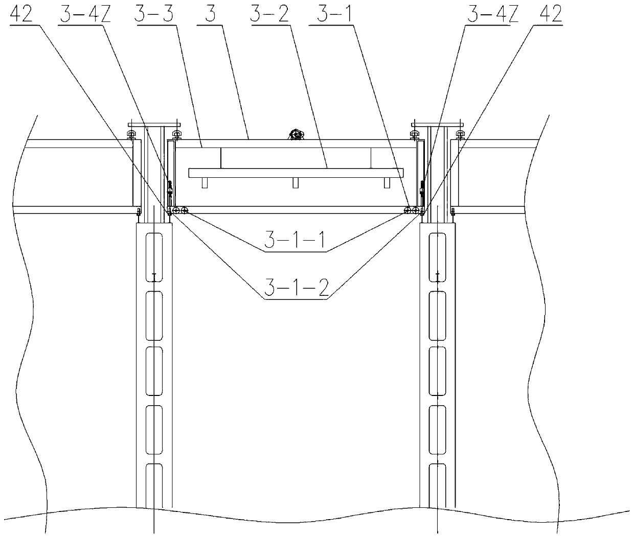
[0047] The container crane 1 includes the transport trolley 3 of the container 2, the track 4 on which the transport trolley 3 runs, the cart 5, the track 6 on which the cart 5 runs, the U-shaped berth 7 and the components 8 on the U-shaped berth 7; the U-shaped berth 7 The length direction of the bottom edge is the X direction, the length of the bottom edge 7X is greater than the width of the container ship 9, the length of the vertical edge 7Y of the U-shaped berth 7 is greater than the length of the ship 9, and the length direction of the container 2 on the ship 9 is parallel to that of the ship 9. In the length direction, when the ship 9 is berthed in the U-shaped berth 7, the length direction of the ship 9 is the Y direction; the member 8 near the ship 9 on the vertical side 7Y is provided with a cart 5 running along the Y direction. The cart Y track 6Y8 , the middle of the upper member 8 on the vertical side 7Y is provided with the longitudinal Y track 41Y8 of the transpo...


PUM


Abstract

A container crane for a U-shaped berth, said container crane comprising transport machines (3) for containers (2), tracks (4) for the transport machines (3) to move along, large machines (5), tracks (6) for the large machines (5) to move along, the U-shaped berth (7), and components (8) on the U-shaped berth (7). Each transport machine (3) comprises a locomotion apparatus (3-1), a spreader and lifting apparatus (3-2), a frame (3-3), and a switching apparatus (3-4), the locomotion apparatus (3-1) being located beneath the frame (3-3), the spreader and lifting apparatus (3-2) being located above the frame (3-3), the frame (3-3) being a hollow cavity with an opening at the bottom. The transport machines (3) on the large machines (5) are used to suspend the containers (2) in the hollow cavities of the frames (3-3), and move along the aerial tracks. The present invention implements full-coverage logistical transportation, and easily achieves automated operations and high efficiency.

Description

technical field [0001] The invention relates to a container crane used for a U-shaped berth, and belongs to the technical field of container logistics transportation. Background technique [0002] The existing container transportation mainly includes chassis vehicle system, straddle carrier system, gantry crane system and hybrid system; 1) chassis vehicle system: the demand for chassis vehicles is large, and the investment is large. The phenomenon of intermittent operation; it is not easy to realize automation; 2) Straddle carrier system: the front of the terminal adopts the container loading and unloading bridge on the shore to undertake the loading and unloading operations of ships, and the straddle carrier undertakes the horizontal transportation between the front of the terminal and the storage yard, as well as the storage of the storage yard. The loading and unloading operations of yards and vehicles entering and leaving the site; the switching of operating areas for st...

Claims


Application Information

Patent Timeline
Patent Type & Authority Patents(China)
IPC IPC(8): B66C19/00B66C9/00
CPCB66C9/00B66C19/002
Inventor 王燏斌
Owner 王燏斌
Learn More