
Mechanical-hydraulic clutch actuator

A clutch control, hydraulic technology, applied in the direction of mechanical drive clutch, non-mechanical drive clutch, clutch, etc.

Active Publication Date: 2017-12-19
ROBERT BOSCH GMBH
View PDF8 Cites 0 Cited by
  • Summary
  • Abstract
  • Description
  • Claims
  • Application Information

AI Technical Summary

Problems solved by technology

[0003] The problem on which the invention is based is solved by a mechanical-hydraulic clutch actuation device

Method used


Image

  • Mechanical-hydraulic clutch actuator
  • Mechanical-hydraulic clutch actuator
  • Mechanical-hydraulic clutch actuator

Examples


Embodiment Construction

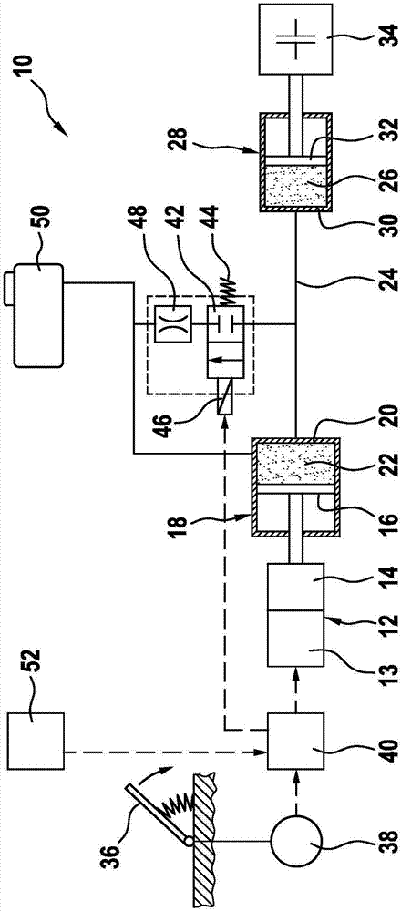
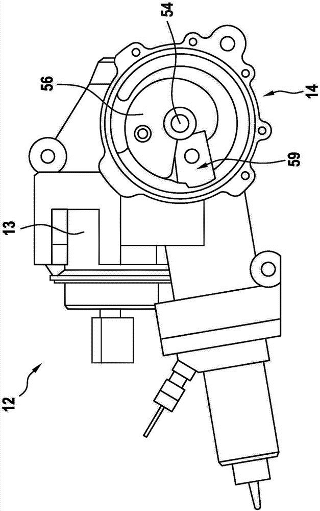
[0029] Mechanical-hydraulic clutch actuation in figure 1 There is generally reference numeral 10 in . (For example electric) driving device 12 belongs to this mechanical-hydraulic clutch operating device, and this driving device comprises electric motor 13 (see figure 2). The transmission 14 belongs to the drive 12 , which here is merely exemplary and is implemented electrically, which in turn is coupled to the piston 16 of the first hydraulic cylinder 18 . The cylinder housing 20 belongs to the first hydraulic cylinder 18 . Together with the piston 16 , the cylinder housing delimits a first pressure chamber 22 . Such clutch actuating devices are therefore also referred to as "electrohydraulic" clutch actuating devices.

[0030] A hydraulic connection line 24 leads from the first pressure chamber 22 to the second pressure chamber 26 of the second hydraulic cylinder 28 . The second pressure chamber 26 is delimited by a cylinder housing 30 and a piston 32 . The piston 32 ...


PUM


Abstract

A mechanical-hydraulic clutch actuator (10) comprises a drive (12) and a first hydraulic cylinder (18), whose piston (16) is coupled at least indirectly with the drive (12) and via a hydraulic connection (24) is hydraulically connected to a second hydraulic cylinder (28) is connected, in turn, with a clutch (34) is operatively connected. It is proposed that the hydraulic connection (24) via a controllable valve means (42) having a low pressure region (50) is connectable.

Description

technical field [0001] The invention relates to a mechanical-hydraulic clutch actuation device according to the preamble of claim 1 . Background technique [0002] In today's motor vehicles with a manual transmission, a mechanically-hydraulic actuated clutch is usually arranged between the internal combustion engine and the transmission. Mechanical actuation usually takes place via an electric drive, which is actuated when the control unit receives a signal from the clutch pedal. The electric drive comprises a control disc, upon rotation of which the piston of the first hydraulic cylinder is actuated. The piston is hydraulically connected to a second hydraulic cylinder, which in turn is operatively connected to the actual clutch. Such a mechanically-hydraulic actuated clutch is described, for example, in DE 10 2013 224 958 A1. Contents of the invention [0003] The problem underlying the invention is solved by a mechanical-hydraulic clutch actuation device. The mechani...

Claims


Application Information

Patent Timeline
Patent Type & Authority Applications(China)
IPC IPC(8): F16D48/02F16D25/08F16D23/12
CPCF16D23/12F16D25/08F16D48/02F16D2048/0251F16D2048/0221F16D2048/023F16D2048/0209F16D2048/0266F16D2048/0263F16D25/14F16D29/005F16D2023/123
Inventor F·戈特瓦尔德
Owner ROBERT BOSCH GMBH
Learn More