High-strength aviation impact-resistant anti-vibration shielding cabinet
A shielding case, anti-shock technology, applied in the fields of magnetic field/electric field shielding, case/cabinet/drawer parts, screening case, etc. Problems such as single form, to achieve the effect of improving work stability, ensuring continuity, and ensuring overall strength
- Summary
- Abstract
- Description
- Claims
- Application Information
AI Technical Summary
Problems solved by technology
Method used
Image
Examples
Embodiment 1
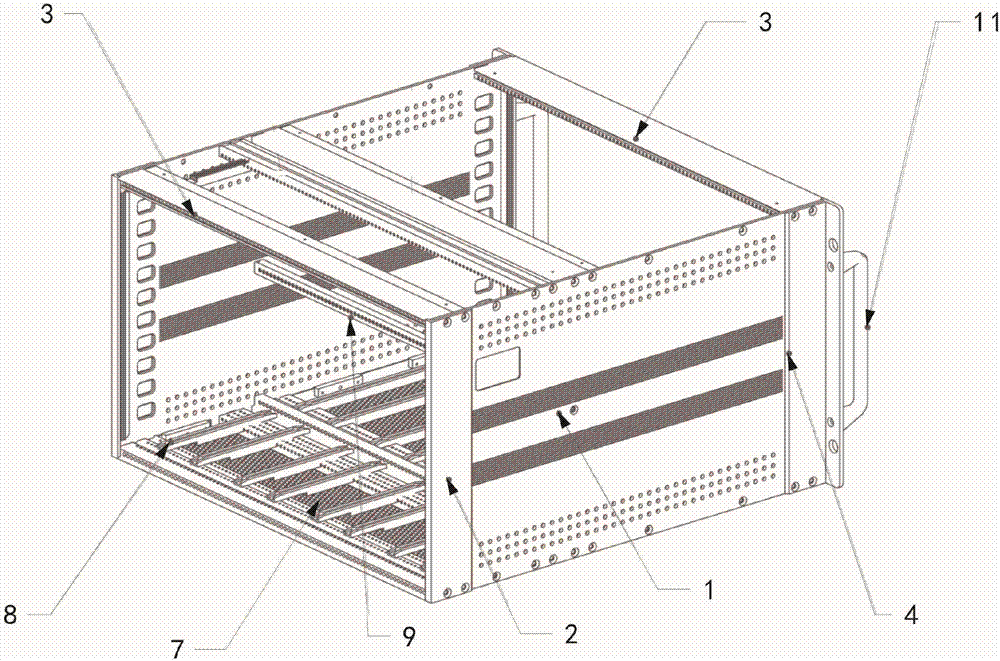
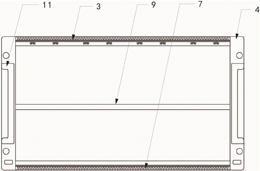
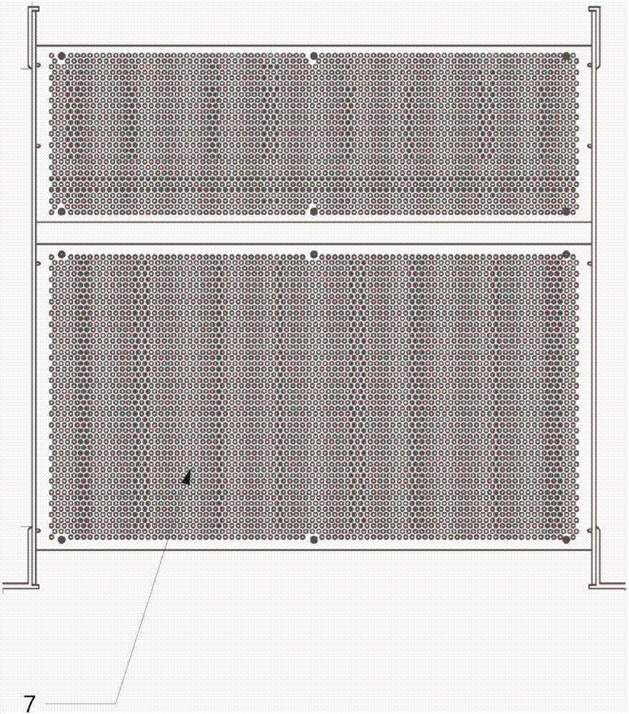
[0030] Such as figure 1 As shown, the present embodiment provides a high-strength aviation anti-shock and anti-seismic shielding cabinet, including two side panels 1 and a rectangular frame 2 parallel to each other, and the rectangular frame 2 is installed between the side panels 1 in parallel; the rectangular frame 2 includes closed beams 3 and reinforced vertical beams 4, the closed beams 3 and reinforced vertical beams 4 are connected by riveting blocks 5 to form a rectangular frame 2; a box includes two sets of rectangular frames 2, and each set of rectangular frames 2 includes two closed Crossbeam 3 and two reinforcing vertical beams 4.
[0031] In order to explain the structure of this embodiment more clearly, the closed beam 3 of this embodiment includes a beam main body 31, and the beam main body 31 is provided with a circular bottom hole 32 for installing a wire screw sleeve and a flat hole for installing a riveting block 5 33 , a special-shaped hole 34 for installin...
Embodiment 2
[0034] This embodiment has made the following optimizations on the basis of Embodiment 1: the two ends of the beam main body 31 in this embodiment are provided with notch positioning grooves 35 for shielding electromagnetic interference, and the notch positioning grooves 35 are divided into convex and concave The mouth uses the form of staggered teeth to strengthen the shielding effect of the edge.
[0035] The working principle of this embodiment is as follows: there are many electronic components inside the box, which generate more electromagnetic interference, and the aircraft needs to shield this unnecessary interference during flight, and the end of the traditional beam needs to be connected to a large number of The grounding copper busbars can effectively seal the electromagnetic interference inside the box, and when the aircraft vibrates, the grounding copper busbars will also vibrate along with it, which is easy to loosen and cause electromagnetic interference leakage; ...
Embodiment 3
[0037] In this embodiment, the following optimizations are made on the basis of Embodiment 1: the special-shaped hole 34 in this embodiment includes a rectangular portion 341 and an arc portion 342, the rectangular portion 341 is located inside the beam main body 31, and the rectangular portion 341 to The distance between the inner sides of the beam main body 31 is most preferably 5mm, and can also be any value between 5mm-6mm.
[0038] The working principle of this embodiment is as follows: the nut strip 6 is a commonly used connector for the aviation shielding cabinet, and various components are installed in the aviation shielding cabinet through the nut strip 6; In the hole 34, when it is necessary to connect components, it can be installed by tapping and drilling. When tapping and drilling, the distance between the special-shaped hole 34 and the inner side of the beam main body 31 is not easy to control. If the distance is too large, it is not easy to drill through. , the ...
PUM
 Abstract
Description
Claims
Application Information
 - R&D
- Intellectual Property
- Life Sciences
- Materials
- Tech Scout
- Unparalleled Data Quality
- Higher Quality Content
- 60% Fewer Hallucinations
Browse by: Latest US Patents, China's latest patents, Technical Efficacy Thesaurus, Application Domain, Technology Topic, Popular Technical Reports.
© 2025 PatSnap. All rights reserved.Legal|Privacy policy|Modern Slavery Act Transparency Statement|Sitemap|About US| Contact US: help@patsnap.com


