
A kind of communication equipment and power-on control method

A technology for communication equipment and electrical control, applied in control/regulation systems, regulating electrical variables, instruments, etc., can solve problems such as large inrush current of the backplane power supply of the equipment, equipment startup failure, and power supply overcurrent protection disconnecting output, etc. Achieve high efficiency and portability, solve accumulated current, and reduce cost of use

Active Publication Date: 2019-03-22
MAIPU COMM TECH CO LTD
View PDF6 Cites 0 Cited by
  • Summary
  • Abstract
  • Description
  • Claims
  • Application Information

AI Technical Summary

Problems solved by technology

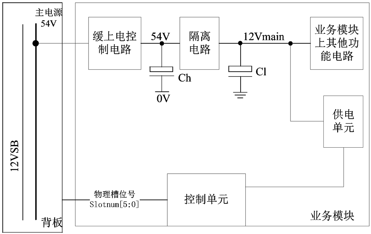
However, when there are many service modules plugged into the equipment frame and powered on (because these service modules will start to be powered on at the same time), it will still cause a large inrush current on the backplane power supply of the equipment, especially when the power supply on the equipment is large. When there are many power business modules (the energy storage capacitor capacity of the corresponding power input processing part will also be large), the cumulative impact current can reach hundreds of amperes, which will not only cause overheating damage to the power connector, but may even cause the power supply to momentarily Overcurrent protection cuts off the output, causing a serious fault event that the device fails to start

Method used


Image

  • A kind of communication equipment and power-on control method
  • A kind of communication equipment and power-on control method
  • A kind of communication equipment and power-on control method

Examples


no. 1 example

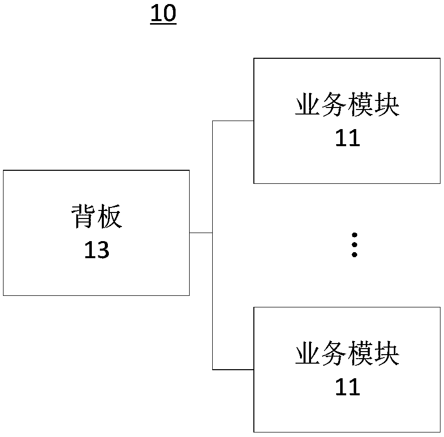
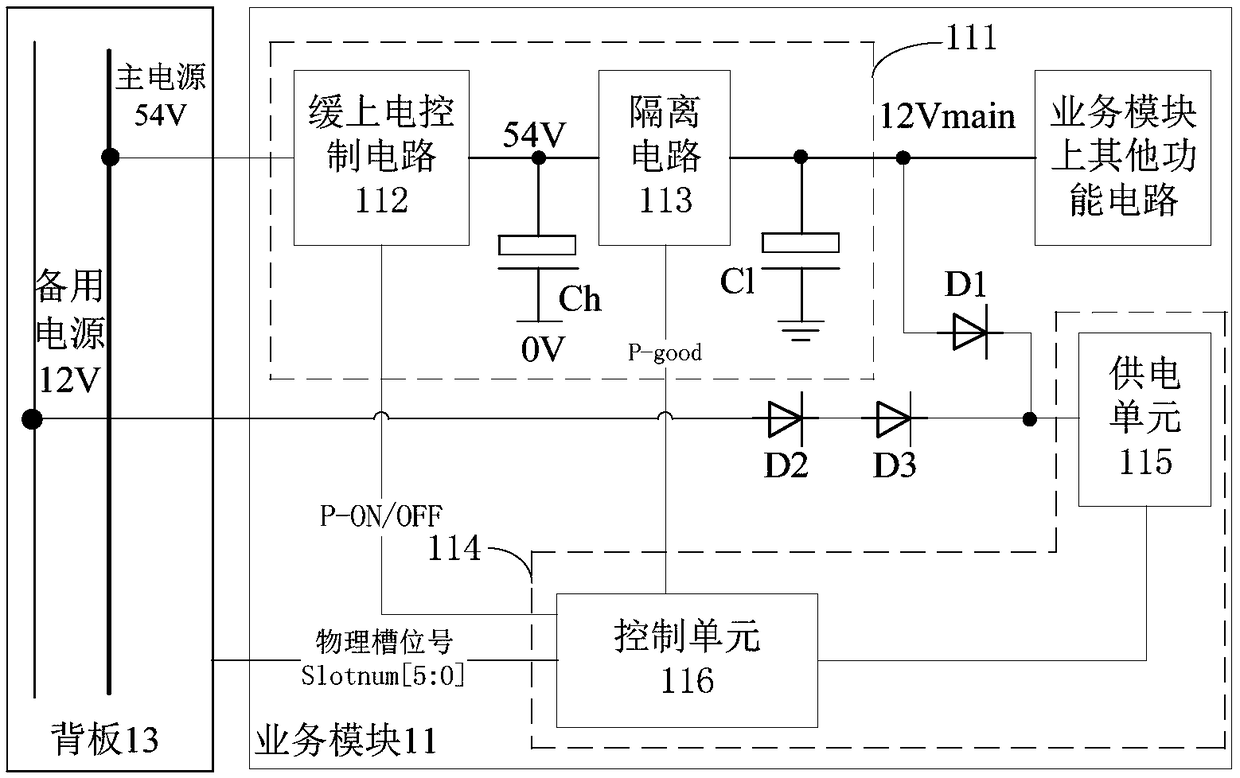
[0024] In view of the fact that there is no good solution to this problem in the equipment design of the industry at present, the designer of the present invention, through long-term exploration and attempts, as well as many experiments and efforts, and continuous reform and innovation, have obtained the solution shown in this solution. communication equipment such as figure 2 shown. The communication device 10 includes: a plurality of service modules 11 and a backplane 13, wherein, please refer to image 3 with Figure 4 , each service module 11 includes: a power input circuit 111 and a control circuit 114; the backplane 13 includes: a backup power supply and a main power supply.

[0025] The power input circuit 111 is connected to the main power supply on the backplane 13, and is also connected to the control circuit 114. When the power input circuit 111 is powered on, the power input circuit 111 is connected to the main power supply. The power input circuit 111 supplies...

no. 2 example

[0037] The power-on control method provided by the present invention is applied to the above-mentioned communication device 10, and will be combined below Figure 4 The steps in the method are described in detail.

[0038] Step S401: During a power supply state in which the backup power supply of the backplane supplies power to the control circuit, control the power input circuit to be powered on through the control circuit.

[0039] When the chassis-type communication equipment is powered on, as long as the 54V main power supply is normal, the main control module (Main Processing Unit, MPU) on the chassis will start to power on and start, which is not subject to any rules. The main power of the module (LPU and / or SFU) will be off by default, and it needs to be turned on according to the rule control sequence. In this way, the 54V main power supply on the communication equipment only has the MPU main control module and the cooling fan module as the starting load. harm.

[0...


PUM


Abstract

The invention relates to communication equipment and a power-on control method, and belongs to the technical field of power source control. The communication equipment includes a plurality of service modules and a backboard, each service module includes a power source input circuit and a control circuit, the power source input circuits and a backup power source of the backboard are all connected with the control circuits, and a main power source of the backboard is connected with the power source input circuits. When the backup power source of the backboard stays at a power supply state for supplying power to the control circuits, each control circuit controls the corresponding power source input circuit to be powered on to make the corresponding power source input circuit stay at a power supply state for supplying power to the control circuit, and the backup power source of the backboard stays at a non-power-supply state without supplying power to the control circuits. The communication equipment, by utilizing resources of itself reasonably, can achieve a delayed power-on function of each service module in order, have high efficiency and portability, require no additional augment of human cost input for researches and development, and reduce the use costs of the equipment.

Description

technical field [0001] The invention belongs to the technical field of power supply control, and in particular relates to a communication device and a power-on control method. Background technique [0002] In the design of modern large-scale communication equipment, based on actual needs such as application flexibility and operational reliability, the equipment system is often designed to support a multi-service module frame structure, and the larger the equipment, the greater the number of supported service module slots At the same time, the service processing capability of this type of equipment is getting stronger and stronger, and the power consumption of a single service module is very large (generally above 300 watts). In order to meet the power consumption requirements of various hardware configurations of the equipment, the power supply of the equipment will also The corresponding design is a multi-module parallel power supply mode. For example, the actual design of ...

Claims


Application Information

Patent Timeline
Patent Type & Authority Patents(China)
IPC IPC(8): G05F1/56
CPCG05F1/561
Inventor 程鸿博
Owner MAIPU COMM TECH CO LTD
Learn More