Power transmission mechanism of marking oscillating device

A power transmission mechanism and equipment technology, applied in the field of power systems, can solve problems such as unreasonable structural design, easy damage, inconvenient installation and disassembly, etc.

Active Publication Date: 2017-12-15
镇江市远宏交通设施有限公司
View PDF8 Cites 0 Cited by
  • Summary
  • Abstract
  • Description
  • Claims
  • Application Information

AI Technical Summary

Problems solved by technology

[0002] At present, in the process of road construction, it is usually necessary to use a marking machine to vibrate the raw materials in the vibrating device. However, the existing vibrating equipment has a very complicated structure and many and huge power transmission routes, which makes the power transmission unreliable, poor in stability and It is easy to be damaged, which affects the quality of work. In addition, it is not very convenient to disassemble and maintain, which reduces the work efficiency, and the cost of use and equipment is very high. Later, someone proposed a power transmission mechanism with reliable power transmission, but its structure Unreasonable design makes installation and disassembly inconvenient and power transmission unstable

Method used


Image

  • Power transmission mechanism of marking oscillating device
  • Power transmission mechanism of marking oscillating device
  • Power transmission mechanism of marking oscillating device

Examples


Embodiment Construction

[0014] The power transmission mechanism of the marking vibration equipment of the present invention will be further described in detail below in conjunction with the accompanying drawings and specific embodiments.

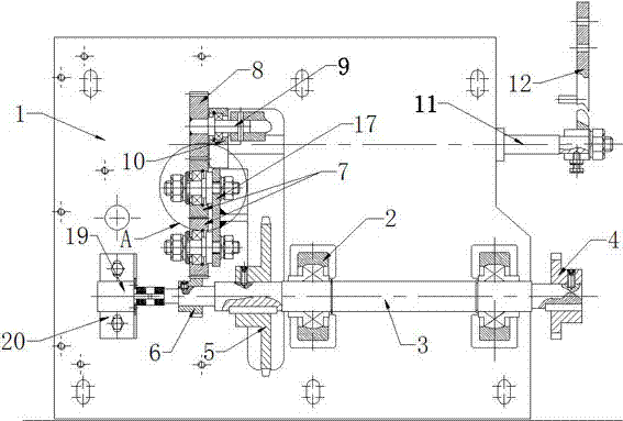
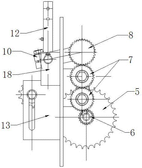
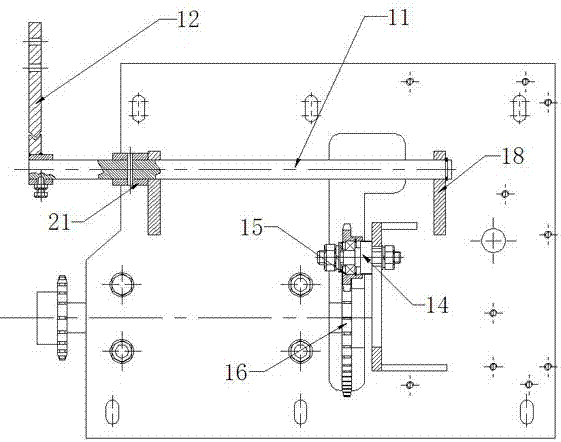
[0015] As shown in the figure, the power transmission mechanism of the marking line vibration equipment of the present invention includes an installation seat plate 1, the front of the installation seat plate 1 is provided with a transmission shaft 3 fixedly installed through a bearing seat 2, and one end of the transmission shaft 3 is installed with The front wheel transfer sprocket 4, the other end is equipped with a traveler transfer sprocket 5, and the transmission shaft 3 is also provided with a transfer shaft gear 6 located outside the traveler transfer sprocket, and the transfer shaft gear 6 passes through a pair of intermeshing transition gears Power transmission is realized between 7 and the spreader transmission gear 8, a transition gear seat 17 is install...


PUM


Abstract

The invention discloses a power transmission mechanism of a marking oscillating device. The power transmission mechanism comprises a mounting seat plate. A transmission shaft is arranged on the front of the mounting seat plate. A front wheel transmission sprocket and a walker transmission sprocket are mounted on the transmission shaft. The transmission shaft is also provided with a transmission shaft gear. Power transmission is realized between the transmission shaft gear and a spreader transmission gear through a pair of transition gears which are meshed. A spreader transmission shaft is mounted on the spreader transmission gear. Flexible shaft transmission movable blocks between which a flexible shaft transmission shaft is mounted are mounted on the spreader transmission shaft. A flexible shaft transmission rod is mounted on the flexible shaft transmission shaft. By adopting the structure, the power transmission mechanism has the advantages of compact structure, low manufacturing cost and capability of ensuring stable operation of a bearing, thereby greatly improving the stability of power transmission and the use reliability, the disassembly is facilitated through the structural design of a positioning sleeve and a clamp spring, the disassembly effect is improved, great convenience is brought to disassembly and maintenance, and the operation efficiency is enhanced.

Description

technical field [0001] The invention relates to a power system of a marking line vibration device, in particular to a power transmission mechanism of a marking line vibration device. Background technique [0002] At present, in the process of road construction, it is usually necessary to use a marking machine to vibrate the raw materials in the vibrating device. However, the existing vibrating equipment has a very complicated structure and many and huge power transmission routes, which makes the power transmission unreliable, poor in stability and It is easy to be damaged, which affects the quality of work. In addition, it is not very convenient to disassemble and maintain, which reduces the work efficiency, and the cost of use and equipment is very high. Later, someone proposed a power transmission mechanism with reliable power transmission, but its structure Unreasonable design makes installation and disassembly inconvenient and power transmission unstable. Contents of t...

Claims


Application Information

Patent Timeline
Patent Type & Authority Applications(China)
IPC IPC(8): E01C23/20
CPCE01C23/20
Inventor 洪亮
Owner 镇江市远宏交通设施有限公司
Why Eureka
Try Eureka