
rotary cam mechanism

A cam mechanism and rotary technology, applied in the field of rotary machine accessories, achieves the effects of simple operation, powerful functions, and convenient continuous production

Active Publication Date: 2019-02-22
GUANGZHOU CHILI AUTOMATION EQUIP
View PDF7 Cites 0 Cited by
  • Summary
  • Abstract
  • Description
  • Claims
  • Application Information

AI Technical Summary

Problems solved by technology

[0003] The technical problem to be solved by the present invention is to provide a rotary cam mechanism to solve the problem that there are many shortcomings in the cam mechanism inside the traditional rotary labeling machine

Method used


Image

  • rotary cam mechanism
  • rotary cam mechanism
  • rotary cam mechanism

Examples


Embodiment Construction

[0017] In the following, numerous specific details are set forth in order to provide a thorough understanding of the concepts underlying the described embodiments. It will be apparent, however, to one skilled in the art that the described embodiments may be practiced without some or all of these specific details. In other instances, well known processing steps have not been described in detail.

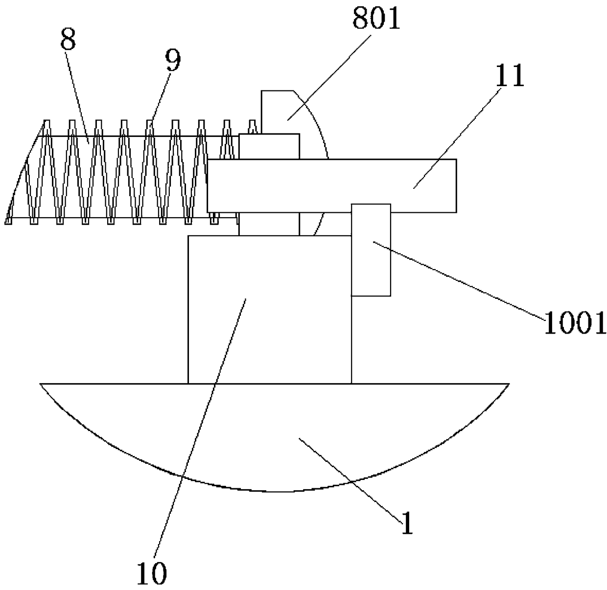
[0018] Such as figure 1 , figure 2 , image 3 As shown, the rotary cam mechanism includes a fixed plate 1, a fixed shaft 2, a rotating shaft 3, a fixed plate 4, a lifting rod 5, a convex plate 6, a baffle plate 7, a sliding rod 8, a spring 9, a rotating shaft 10, and a connecting rod 11 , the pressure plate 12, the fixed shaft 2 is located at the middle end of the top of the fixed plate 1, the fixed shaft 2 is closely connected with the fixed plate 1, the rotating shaft 3 is located at the top of the fixed shaft 2, and the rotating shaft 3 is connected to the fixed shaft 2 in rot...


PUM


Abstract

The invention discloses a rotary type cam mechanism. The rotary type cam mechanism comprises a fixing disc, a fixing shaft, a rotating shaft, a fixing plate, a lifting rod, a convex plate, a baffle, a sliding rod, a spring, a revolving shaft, a connecting rod and a pressing disc. According to the rotary type cam mechanism, the structure is smart, and the function is powerful; by using the device, rotating and resetting of the pressing disc are achieved, so that continuous production of later label is facilitated, in addition, adjusting of the height of the convex plate can be realized through simple operation; and ultimately, time saving and labor saving are achieved, and at the same time, stability of whole machine operation is further promoted greatly.

Description

technical field [0001] The invention relates to the field of rotary machine accessories, in particular to a rotary cam mechanism. Background technique [0002] In the current packaging industry, rotary labeling machines are widely used due to their stable performance, fast labeling speed and high precision. But there are many deficiencies in its key part cam mechanism: 1, the cam is heavy and has more than 600 kilograms, it is inconvenient to replace, many people need to carry it, it takes a lot of work and time, and it is not safe. 2. The material requires high hardness, difficult processing, and long cycle time. It will be easily deformed during processing, and a slight mistake will result in scrapping. 3. The friction of the cam is large during operation, which produces a lot of noise and vibration, which affects the surrounding environment; frequent refueling and replacement of accessories increase the cost. 4. The design of the cam is complicated. One bottle shape and...

Claims


Application Information

Patent Timeline
Patent Type & Authority Patents(China)
IPC IPC(8): B65C9/00
CPCB65C9/00
Inventor 邓敏辉谢继华黄文标
Owner GUANGZHOU CHILI AUTOMATION EQUIP
Learn More