
Visible self-locking fixed placer of cavity-closed drainage tube

A drainage tube and cavity-closed technology, which is applied in the field of cavity-closed drainage tube placement, can solve the problems of patients’ pain, increased chest wall blood vessels, difficult to control bleeding, etc., achieve a reasonable overall design, reduce medical operations, and avoid subcutaneous gas swollen effect

Pending Publication Date: 2017-12-15
姜峰 +1
View PDF1 Cites 2 Cited by
  • Summary
  • Abstract
  • Description
  • Claims
  • Application Information

AI Technical Summary

Problems solved by technology

[0004] Although the above solution solves the deficiencies of the prior art to a certain extent, the material of the drainage tube is relatively soft, and when it penetrates into the patient's chest cavity, it needs to be inserted by clamping the drainage head of the drainage tube with an auxiliary tool. method, it is necessary to separate the chest wall muscle layer and intercostal muscles to establish a sufficient tunnel space, even under adequate local anesthesia, too much blunt separation of the chest wall muscle layer and intercostal muscles will cause great pain to the patient At the same time, it increases the probability of chest wall vessel and intercostal vessel injury, which may lead to uncontrollable bleeding, and even accidentally injure the diaphragm, liver and spleen; the front end of the drainage tube does not have a camera, and the drainage situation cannot be directly observed, and the overall design is not reasonable enough

Method used


Image

  • Visible self-locking fixed placer of cavity-closed drainage tube
  • Visible self-locking fixed placer of cavity-closed drainage tube
  • Visible self-locking fixed placer of cavity-closed drainage tube

Examples


Embodiment Construction

[0026]The following will clearly and completely describe the technical solutions in the embodiments of the present invention with reference to the accompanying drawings in the embodiments of the present invention. Obviously, the described embodiments are only some, not all, embodiments of the present invention. Based on the embodiments of the present invention, all other embodiments obtained by persons of ordinary skill in the art without creative efforts fall within the protection scope of the present invention.

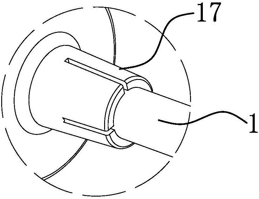
[0027] Such as Figure 1-4 As shown, this visible self-locking and fixed closed-cavity drainage tube placer includes a tube core 2 that can be inserted into one end of the drainage tube 1 and is made of hard material, and an internal positioning mechanism arranged on the outside of the drainage tube 1 3 and the outer positioning mechanism 4, the outer positioning mechanism 4 can approach or move away from the inner positioning mechanism 3 axially along the drainage ...


PUM


Abstract

The invention belongs to the technical field of medical apparatus and instruments, and particularly relates to a visible self-locking fixed placer of a cavity-closed drainage tube. The placer comprises a pipe core which can be inserted in one end of the drainage tube and is made of a hard material, and an inner positioning mechanism and an outer positioning mechanism which are arranged on the outer side of the drainage tube; the outer positioning mechanism can be close to or away from the inner positioning mechanism in the axle direction of the drainage tube and can be locked to the drainage tube axially, a positioning zone is formed between the inner positioning mechanism and the outer positioning mechanism, and the hardness of the pipe core is larger than that of the drainage tube; a limit structure is arranged between the pipe core and the drainage tube, wherein after the pipe core is inserted into the drainage tube, the limit mechanism can prevent the pipe core from breaking away from the front end of the drainage tube, and an image collection component which can be exposed out of the front end of the drainage tube is arranged at the front end of the pipe core. The placer has the advantages that the inner portion and the outer portion of the placer can be locked, falling of the drainage tube or subcutaneous emphysema is avoided, the drainage tube directly penetrates through the chest of a patient conveniently, and the drainage situation in the chest can be directly observed.

Description

technical field [0001] The invention belongs to the technical field of medical devices, in particular to a visible self-locking and fixed cavity-closed drainage tube placement device. Background technique [0002] Closed thoracic drainage is an effective method for treating empyema, traumatic hemothorax, pneumothorax, and spontaneous pneumothorax. measure. However, there are many shortcomings in the existing closed chest drainage tube, which lead to complicated operation, as follows: 1. Because the material of the existing closed chest drainage tube is soft, when it is inserted into the chest cavity of the patient, it needs to be clamped with an auxiliary tool The drainage head of the drainage tube can only be inserted. This method of delivery requires separation of the chest wall muscle layer and intercostal muscles to establish a sufficient tunnel space. Even under adequate local anesthesia, excessive blunt separation of the chest wall muscles The intercostal muscles and...

Claims


Application Information

Patent Timeline
IPC IPC(8): A61M25/10
CPCA61M25/0017A61M25/10
Inventor 姜峰王临焦亚桂焦大勇
Owner 姜峰
Learn More